Thanks for the interest in our project! While we work to recreate a Polywell our main motivation is in the engineering challenges in doing so. We are just two engineering students working on it in our free time and we do not have any funding (except for the donations and loans of some equipment).
With regard to the text on our website, yes there was a mix up between anode and cathode, and bucky and wiffle ball. That should be corrected now.
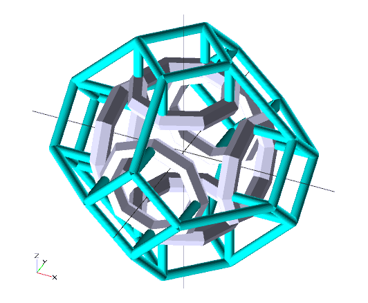
The drawing is not a final design but an initial practical design. We are aware of the associated disadvantages of having the coil interconnects near the virtual cathode and a square cross-section.
However we are limited by the resources (basic machining equipment) available to us. We do not believe that a 3D printed magrid is a viable (and affordable) possibility and thus plan to machine the coil housings from aluminium. This makes it difficult to create a round cross-section.
The interconnects are difficult to connect to the round sides of the coil housing (without welding them on) and are thus placed on the flat bottom (although we are looking into how we could connect them to the round sides).
This current design would allow for a completely sealed coil housing preventing any exposure of the coils to the vacuum and providing the possibility of adding cooling or electrically separating the coils from the housing. Additionally the interconnects could be replaced to vary the coil spacing.
As usual there is always a trade-off and this design will certainly not be the last.
So don't expect any ground breaking results from us. We just hope to give a practical approach to a functioning Polywell (with or without measurable fusion) with better plasma diagnostics than the previous amateur project.
Radiant Matter Research - The Polywell In The Neatherlands
-
Radiant Matter
- Posts: 3
- Joined: Wed Oct 16, 2013 9:12 am
Re: Radiant Matter Research - The Polywell In The Neatherlan
Well, I for one, am really impressed by the resourcefulness and dedication to your project. I also feel that a continuous operation would be impressive. The issues I might think of for the coil casing is sharp corners leading to problems with high voltage, also as long as the coil side facing the plasma conforms to the magnetic field (I would think) it should be ok. In that regard, perhaps a pipe bent into the shape of a donut (back side cut off), bolted to a backing ring, where the interconnects are on the back side away from the plasma might be an idea. If you had six flanges, then each coil could be attached to its own flange.
It is easy for me to make suggestions, but you are the guys doing the work and getting the parts and money. All I can say, again, is bravo! My hat is in my hands.
Very best regards,
Mike
PS As we don't have any hardware projects on this site, maybe we could organize some support funding. It might help to have a breakdown of parts and cash needed so we can work towards meeting and facilitating those hardware steps.
What do you guys on the site say?
Counting the days to commercial fusion. It is not that long now.
Re: Radiant Matter Research - The Polywell In The Neatherlan
I favor the magrid coils being supported from outside.
The daylight is uncomfortably bright for eyes so long in the dark.
Re: Radiant Matter Research - The Polywell In The Neatherlan
The rounded magrid casings were the 'eureka' moment which made Polywell possible (WB-6). I don't think you need to use 3D printing.
Get a truck exhaust shop to bend >180deg toroidal arcs in stainless steel (SS) tubing, cut at 180deg, weld halves, grind or turn smooth and cut apart around the 'equator' (using 'inside' and 'outside' chucks on a metal lathe). Then weld on and grind or turn smooth two machined and threaded SS joining rings (conforming to the round outer profile after smoothing the welds). Assemble with small SS threaded fasteners. Widely available equipment: tubing bender, MIG welder, metal lathe, grinder, drill press, taps.
http://www.youtube.com/watch?v=gmpS_99zCjc
There are alternatives such as making a custom, inside/outside torus-turning tool holder for a lathe, lost foam casting in aluminum or welding a polygonal approximation to a torus, but I think the tubing bender approach would be the quickest and cheapest, with acceptable accuracy.
-
Radiant Matter
- Posts: 3
- Joined: Wed Oct 16, 2013 9:12 am
Re: Radiant Matter Research - The Polywell In The Neatherlan
From our experience with Hirsch-Farnsworth Fusors we do not expect sharp corners to give a lot of problems with respect to electric discharges at the expected working pressures < 1e-3 mbar (although we are familiar with the discharges to the walls Bussard encountered).
Crossing the field lines might be slightly more disadvantageous but the question remains whether or not the extra work is worth the trouble for an initial version. If we want we could at some point invest the work of milling the bottom of the coil covers round. Also we are already maximizing the area in the oval shape of the field lines near the coils by using a flange and thin wall.
We have experimented with bending a pipe (annealed copper) in the required radius but that did not give a small enough radius at the required tube diameter (~15mm). Keep in mind our chamber is 300mm in diameter and our access port is 150mm wide (8" CF flange). This means that the coils can be at most have an OD of 80mm(assuming ~20mm thickness).
The current design is meant merely as a test setup for the basic principles and equipment.
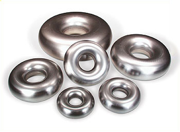
If we would want to build a best performance model we would probably use pre-made aluminium donuts like:
https://www.google.nl/search?q=aluminiu ... t&tbm=isch (probably made using metal spinning)
and skip any possibility of cooling the coils. However these 'donuts' are relatively expensive and do not provide the flexibility of the current design.
Any experiment attempting to come close to the performance of a WB-6 will require a much larger vacuum chamber and of course the necessary large coil power and bias supplies (and larger electron sources, ionization sources/ion guns, etc.).
Crossing the field lines might be slightly more disadvantageous but the question remains whether or not the extra work is worth the trouble for an initial version. If we want we could at some point invest the work of milling the bottom of the coil covers round. Also we are already maximizing the area in the oval shape of the field lines near the coils by using a flange and thin wall.
We have experimented with bending a pipe (annealed copper) in the required radius but that did not give a small enough radius at the required tube diameter (~15mm). Keep in mind our chamber is 300mm in diameter and our access port is 150mm wide (8" CF flange). This means that the coils can be at most have an OD of 80mm(assuming ~20mm thickness).
The current design is meant merely as a test setup for the basic principles and equipment.
If we would want to build a best performance model we would probably use pre-made aluminium donuts like:
https://www.google.nl/search?q=aluminiu ... t&tbm=isch (probably made using metal spinning)
and skip any possibility of cooling the coils. However these 'donuts' are relatively expensive and do not provide the flexibility of the current design.
Any experiment attempting to come close to the performance of a WB-6 will require a much larger vacuum chamber and of course the necessary large coil power and bias supplies (and larger electron sources, ionization sources/ion guns, etc.).
Re: Radiant Matter Research - The Polywell In The Neatherlan
Based on your goals for this stage, that all makes sense to me. So, where do you stand on implementation progress?
Best regards,
Mike
Best regards,
Mike
Counting the days to commercial fusion. It is not that long now.
Re: Radiant Matter Research - The Polywell In The Neatherlan
Thanks for the link! I had no idea that premade metal-shell tori were available:
http://www.pro-werks.com/categories/843/
These are intended to be cut at whatever angle is needed for custom exhaust or intake fabrication. Available in aluminum, mild steel or stainless steel.
http://www.pro-werks.com/categories/843/
These are intended to be cut at whatever angle is needed for custom exhaust or intake fabrication. Available in aluminum, mild steel or stainless steel.
Re: Radiant Matter Research - The Polywell In The Neatherlan
That's sooooo cool!
Counting the days to commercial fusion. It is not that long now.
Re: Radiant Matter Research - The Polywell In The Neatherlan
Just to Nit pick, in my opinion, the round casings were helpful, but the "Eureka" moment was the realization that the magnets needed to be spaced apart. This is what allows for recirculation to proceed efficiently. With WB4 (and WB5) the dog house interconnects and cans actually touched on the sides, any electrons escaping on the sides (not face centered point cusps) were more than likely to hit the magnets. So recirculation, while possible,-in fact dictated by the physics, was significantly constrained by the magnet impacts. There was recirculation with WB4, it is just that with the spacing (and rounded surfaces), the allowable recirculation in WB6 was ten times greater or more (see below).DeltaV wrote:The rounded magrid casings were the 'eureka' moment which made Polywell possible (WB-6). I don't think you need to use 3D printing.
Get a truck exhaust shop to bend >180deg toroidal arcs in stainless steel (SS) tubing, cut at 180deg, weld halves, grind or turn smooth and cut apart around the 'equator' (using 'inside' and 'outside' chucks on a metal lathe). Then weld on and grind or turn smooth two machined and threaded SS joining rings (conforming to the round outer profile after smoothing the welds). Assemble with small SS threaded fasteners. Widely available equipment: tubing bender, MIG welder, metal lathe, grinder, drill press, taps.
http://www.youtube.com/watch?v=gmpS_99zCjc
There are alternatives such as making a custom, inside/outside torus-turning tool holder for a lathe, lost foam casting in aluminum or welding a polygonal approximation to a torus, but I think the tubing bender approach would be the quickest and cheapest, with acceptable accuracy.
Bussard pointed this out. It was his/ their mental picture of the electromagnets as simple mathematical lines (with zero width and thus no vulnerable impact surface area) that was recognized as an unrealistic flaw.
That is why he moved the magnets apart. This weakened the mid plane magnet strength between them, but even with this effectively wider cusp that was necessary for recognized ExB drift issues, the final performance improved 10X. Even with WB6's spacing and much smaller nubs, EMC2 realized with WB7 that further improvement over WB6 configurations was desirable, and possible(?).
I have a mental picture that cusp confinement improved to Wiffleball confinement resulted in electron confinement of perhaps a factor of ~ 5000 passes in WB4. The available recirculation in WB4 may have improved electron retention to ~ 10,000 passes. In WB6 the Wiffleball confinement may have suffered. Say the confinement was 4000 passes. But the recirculation may have improved more than 10 fold compared to WB4, so that the final efficiency was ~ 100,000 passes. Nebel's comments about WB7.0 and assumed nub changes to WB7.1 may have suggested increased even more recirculation efficiency.
Much of the Polywell scheme is a compromise. I think WB4 had superior electron magnetic containment than WB6 (ignoring square can contributions). But once confinement was lost though the cusps, only a relative few electrons were able to recirculate due to the large metal exposures across the side/ corner cusps. WB5 tried to address this through plugging the cusps, effectively improving electron confinement. Even with this, the electron potential well was weak, and hopes of driving the well to greater levels with increased input was frustratingly marginal. I don't know how much the ion loss was tied in with this, but it allowed Bussard etel to realize that magnetic cusp confinement even with Wiffleball effect and even cusp plugging was not capable of suppressing losses enough. Only then did Bussard realize that confinement plus the all important recirculation was the path to claimed success. The compromise of less efficient magnetic electron confinement and perhaps even a small drop in the Wiffleball trapping factor was more than made up for by relatively large recirculation of the electrons. Remember that recirculation of the electrons is essentially a direct conversion grid. The escaping electrons give up their KE as they fly outward past the magrid. Once stopped they are re accelerated back inside with the stored energy of the magrid. This not only recirculates the non upscattered electrons at near zero energy cost, it results in electron injection energy at mono energetic conditions. The down scattered escaping electrons gain energy upon recirculation, the up scattered electrons carry away energy, but only that portion beyond the magrid accelerating voltage. Thus there is a restoring force acting on the thermalising electrons that doesn't cost nearly as much energy as using electron gun derived electrons to replace all escaping electrons. So, not only is the energy cost improved with recirculation, the possibly shorter magnetic confinement time for the average electron would slow the thermalization of the overall electron population- they get replaced more rapidly by a costly electron gun input and a much less costly recirculation). Add to this the shorter confinement time (travel faster so shorter times to cusp escape (say 10,000 passes )) of the up scattered electrons results in a further impediment to full thermalization (especially of the high energy tail) . This does cost energy, but only that in excess of the recirculating voltage. Recirculation not only saves on the total electron energy bill, it also provides for beneficial removal of up scattered electrons at modest energy costs. A win- win situation that I don't think is available through tighter cusp confinement alone, or with cusp plugging schemes. For several reasons it is the best compromise.
Dan Tibbets
To error is human... and I'm very human.
Re: Radiant Matter Research - The Polywell In The Neatherlan
Thanks, Dan, you are correct about the extra spacing also being part of the 'eureka' moment.
The "donuts" (I had earlier been searching "torus", "tori", "toroidal"... doh) retail for around $150-$200 each. Polywell experimenters, however, would prefer them unwelded for coil winding purposes, and perhaps also adding drilled/tapped joining rings so that they could be disassembled downstream, instead of "weld and forget".
Maybe pro-werks.com would drop the price for unwelded versions, since that saves them a lot of manufacturing time. It looks like they offset the seams, probably so that the donuts will lay flat for grinding the welds.
Heck, if enough people ask about it, they might also provide other aspect ratios (major/minor diameters). The fat donuts seem better for higher amp-turns and B-field strength, with smaller alpha escape cusps, but the optimum aspect ratio could well require skinnier donuts.
Re: Radiant Matter Research - The Polywell In The Neatherlan
Same here, but I would align the supports radially, keeping them in the 'shadows'.hanelyp wrote:I favor the magrid coils being supported from outside.
Re: Radiant Matter Research - The Polywell In The Neatherlan
As I understand RMR's current incremental step, the goal is to demonstrate that they can make, run, test, and evaluate the data for the basic polywell device in a small, relatively inexpensive device. After that, it should be easier to get the resources to go to the next level. To include demonstrating a SC powered, continuous magnetic device in this build, is itself a big deal. I am not sure of their thinking here on why that jump is right for this build. Perhaps there are multiple steps in this build and the SC magnetics is a later stage.
Do I have that right?
Do I have that right?
Counting the days to commercial fusion. It is not that long now.
-
Radiant Matter
- Posts: 3
- Joined: Wed Oct 16, 2013 9:12 am
Re: Radiant Matter Research - The Polywell In The Neatherlan
As to the question about the project status:
The vacuum system has been changed from a diffusion pump to a turbo pump. The vacuum chamber has been completely cleaned and most seals are now copper. A 6" Conflat extension has been added to the vacuum chamber which will house a small Farnsworth Fusor as test source for the neutron detectors.
We have started work on a prototype aluminium coil housing to test some different ideas for the interconnects and to test the planned viton seals.
The motorized monochromator we plan to use for the plasma spectroscopy requires further testing for which we will also use the small Farnsworth Fusor. We have most of the mechanical parts for a moveable Langmuir probe ready but we still have to build the voltage sweep circuitry. Next we want to compare the results from the plasma spectroscopy and Langmuir probe using some test plasmas.
The final step will be to build the 'continuous' (battery) and pulsed (capacitor bank) coil power supply.
As for the superconducting Polywell, it is more of a final goal than a practical plan. We have looked into the possibility of making YBCO ourself and while that is relatively simple YBCO is difficult to convert into a useful shape (e.g. powder-in-wire doesn't work). (The proposed prototype is also a test for the possibility of using ln2 cooled sc coils, by replacing the viton seals with indiium. Big question is ofcourse external heat load, required additional insulation/cooling etc.)
We are first going to build the proposed prototype and based on the results we will plan the next iteration.
Re: Radiant Matter Research - The Polywell In The Neatherlan
Keep us posted RM!
I feel that it is efforts like yours that stand a chance of making some progress and validating this technology -- if you can suffer the costs and the setbacks you will no doubt encounter daily.
I feel that it is efforts like yours that stand a chance of making some progress and validating this technology -- if you can suffer the costs and the setbacks you will no doubt encounter daily.