I hate to be the one to dismantle my own arguments, but I've been thinking about the line of reasoning I used in the thread All that can go wrong with recirculation. It is correct that in the ideal, symmetrical case, the central field line of a cusp will go to infinity, and the field lines within an electron gyroradius of that will make big, big loops. But what if you break the symmetry?
Think of adding a smallish transverse field outside the coils. This should sweep the flux tube coming from the cusp to the side, where it might remain in a region with significant field strength and loop back in some reasonable distance. (Getting all of these flux tubes to loop back to another cusp is likely to remain a problem, as well as other issues I identified, but let's take one thing at a time.) At the same time, some other flux tube, an innocent bystander, will be bent out and become the one that goes to infinity.
Another way to look at this is that the field lines near the field maximum all look about the same. It is not possible to identify locally which field line has the global topological property of penetrating to the field-free interior, nor is it not possible to identify the one that breaks free on the outside. Why, then, must these two special field lines be identical (except by symmetry arguments, that I want to relax here)?
I'm not clear on the implications of this line of thought, and I don't have much time to work them out now, but I thought I should throw it out anyway.
Recirculation revisited
-
Art Carlson
- Posts: 794
- Joined: Tue Jun 24, 2008 7:56 am
- Location: Munich, Germany
I don't think looping is much of a factor. Electrons of a low enough energy will oscillate. Above that energy they will hit a wall.
The oscillation will cause a bunching. The bunching will tend to equilibrate particle energies. Klystron like. The oscillation has the advantage of sweeping the velocity space as well as the physical space.
Of course not having done the math (I leave that to the physicists) the above is only an opinion. However, it is informed by some simulations I have seen.
Engineering is the art of making what you want from what you can get at a profit.
-
alexjrgreen
- Posts: 815
- Joined: Thu Nov 13, 2008 4:03 pm
- Location: UK
Computer Space Plasma Physics:MSimon wrote:Of course not having done the math (I leave that to the physicists) the above is only an opinion. However, it is informed by some simulations I have seen.
Simulation Techniques and Software
http://www.terrapub.co.jp/e-library/cspp/index.html
Chapter 5 is useful.
Kip Thorne's course material for Academic Year 2004-2005
Ph 136: APPLICATIONS OF CLASSICAL PHYSICS,
including the text of his book with Roger Blandford
http://www.pma.caltech.edu/Courses/ph136/yr2004/
Chapters 18-22 are relevant.
Ars artis est celare artem.
-
Mike Holmes
- Posts: 308
- Joined: Thu Jun 05, 2008 1:15 pm
Sounds a little like my idea (somebody had it before me, I recall) of encasing the cube inside an octahedron with a field over each cusp. To the uneducated, at least. What I referred to as "Capping the holes."
This, of course, would horrifically complicate any attempt to extrapolate from a simulation what the results would be (as I think MSimon noted), and I'm not sure that a conducive geometry exists for this configuration. But, intuitively, what I'm thinking would happen if you could set it up right, is that the cusp losses would be reduced to further cusp losses on the "outside shell," if I might. Basically you reduce the losses at each shell, causing more and more recirculation.
You could then, in theory, implement as many such "shells" as you needed to ensure that losses were at an acceptable level.
I'm quite sure that there's something terribly wrong with this idea, of course (after all, I came up with it), but I'm just throwing it out there for brainstorming purposes. Emboldened by Dr. Carlson's thoughts.
By the way, these Platonic solids are interesting. A dodecahedron has 20 vertices, the same as the number of sides on an Icosahedron.
I think that the Romans were building a dodec Polywell: http://en.wikipedia.org/wiki/Roman_dodecahedron

Mike
This, of course, would horrifically complicate any attempt to extrapolate from a simulation what the results would be (as I think MSimon noted), and I'm not sure that a conducive geometry exists for this configuration. But, intuitively, what I'm thinking would happen if you could set it up right, is that the cusp losses would be reduced to further cusp losses on the "outside shell," if I might. Basically you reduce the losses at each shell, causing more and more recirculation.
You could then, in theory, implement as many such "shells" as you needed to ensure that losses were at an acceptable level.
I'm quite sure that there's something terribly wrong with this idea, of course (after all, I came up with it), but I'm just throwing it out there for brainstorming purposes. Emboldened by Dr. Carlson's thoughts.
By the way, these Platonic solids are interesting. A dodecahedron has 20 vertices, the same as the number of sides on an Icosahedron.
I think that the Romans were building a dodec Polywell: http://en.wikipedia.org/wiki/Roman_dodecahedron
Mike
Again I come back to the fact that the holes are ALREADY capped by the electric field. Would someone please explain in simple words the problem that this "capping" is supposed to solve?Mike Holmes wrote:Sounds a little like my idea (somebody had it before me, I recall) of encasing the cube inside an octahedron with a field over each cusp. To the uneducated, at least. What I referred to as "Capping the holes."
-
Mike Holmes
- Posts: 308
- Joined: Thu Jun 05, 2008 1:15 pm
The long-line cusp escapes, the "central" ones that go to infinity.
I can't counter you, and say that these aren't already "capped" by the electric field, maybe you're right. I'm just saying that, if such a problem does exist, as Art Carlson seems to believe, that this might be a solution.
I'll leave it to you two to argue whether the problem exists or not.
Mike
I can't counter you, and say that these aren't already "capped" by the electric field, maybe you're right. I'm just saying that, if such a problem does exist, as Art Carlson seems to believe, that this might be a solution.
I'll leave it to you two to argue whether the problem exists or not.
Mike
-
alexjrgreen
- Posts: 815
- Joined: Thu Nov 13, 2008 4:03 pm
- Location: UK
The magrid is held at positive potential, so electrons that escape from the wiffle ball will either have so much energy that they hit the wall orKitemanSA wrote:Again I come back to the fact that the holes are ALREADY capped by the electric field.
1. Be accelerated to the magrid.
2. Be decelerated as they pass it.
3. Stop.
4. Be accelerated back to the magrid.
5. Be decelerated as they pass it on their way back to the wiffle ball.
What proportion of them find their way back into the wiffle ball is the important question.
Ars artis est celare artem.
So far so good, I think. I am presuming that the ones that "hit the wall" are those that have acquired so much energy that the positive grid cannot decelerate them enough (or in time).alexjrgreen wrote:The magrid is held at positive potential, so electrons that escape from the wiffle ball will either have so much energy that they hit the wall orKitemanSA wrote:Again I come back to the fact that the holes are ALREADY capped by the electric field.
1. Be accelerated to the magrid.
2. Be decelerated as they pass it.
3. Stop.
4. Be accelerated back to the magrid.
5. Be decelerated as they pass it on their way back to the wiffle ball.
What proportion of them find their way back into the wiffle ball is the important question.
But as for the rest, I was under the impression that they would:
A: decelerate along a magnetic field line due to the electric field, stop, and retrace it's path back via the same magfield line thru the same cusp
OR
B: track a close loop around from one cusp to the next and re-enter that way.
If this is NOT correct, could someone, in words simple enough for a mere mechanical engineer, explain why?
Thanks
Like I said in the other thread, putting mirror coils outside the maggrid will ensure a boundary for the maggrid field inside the chamber if it is required. It's just like the image solution used earlier to find approximate wiffleball field, except the maggrid would be the inner coil and would be real not an image.
Carter
I made my animation showing B. Then I was told that was wrong, A would occur, the electron sort of surfing field lines, back and forth then returning thru the same cusp.KitemanSA wrote:
But as for the rest, I was under the impression that they would:
A: decelerate along a magnetic field line due to the electric field, stop, and retrace it's path back via the same magfield line thru the same cusp
OR
B: track a close loop around from one cusp to the next and re-enter that way.
If this is NOT correct, could someone, in words simple enough for a mere mechanical engineer, explain why?
Thanks
I like the p-B11 resonance peak at 50 KV acceleration. In2 years we'll know.
Yes, and in a real physical device it would be impossible to get the coil/field alignments perfect anyway. The symmetry is broken by some small amount by unavoidable fabrication imperfections. How much does it need to be broken by? 1 gyro radius?It is not possible to identify locally which field line has the global topological property of penetrating to the field-free interior, nor is it not possible to identify the one that breaks free on the outside. Why, then, must these two special field lines be identical (except by symmetry arguments, that I want to relax here)?
To state the blindingly obvious. There will be a trade-off between making the inside field symmetrical enough to keep the plasma ball accurate and the outside field asymmetrical enough to keep those 2 special field lines separated.
Applying outside fields as Art suggests to offset them could decouple the problems but there will be some effect on the inside fields by the external bias field.
I wonder if the fields from the electrical feed lines would be enough to break they symmetry?
Does anyone (who's talking) have any clue as to just how accurately balanced the inside fields need to be to keep the plasma from squirting out a weak point?
We could compare that with the field shift needed to offset the 2 special field lines by 1 gyro-radius (as a wild guess).
-Tom Boydston-
"If we knew what we were doing, it wouldn’t be called research, would it?" ~Albert Einstein
"If we knew what we were doing, it wouldn’t be called research, would it?" ~Albert Einstein
You guys are confusing the heck out of me!tombo wrote:Does anyone (who's talking) have any clue as to just how accurately balanced the inside fields need to be to keep the plasma from squirting out a weak point?
Why would the plasma "squirt" out anywhere? The plasma (which I am reading as the ions) is retained by the virtual cathode, no? The virtual cathode is retained by the MaGrid. No?
But I don't yet get why we CARE if the "flux tubes" loop back.Art Carlson wrote:(Getting all of these flux tubes to loop back to another cusp is likely to remain a problem, as well as other issues I identified, but let's take one thing at a time.)
I guess my question is, just what is the magnitude of this problem? Is this an exercise in guilding the lily?
-
Art Carlson
- Posts: 794
- Joined: Tue Jun 24, 2008 7:56 am
- Location: Munich, Germany
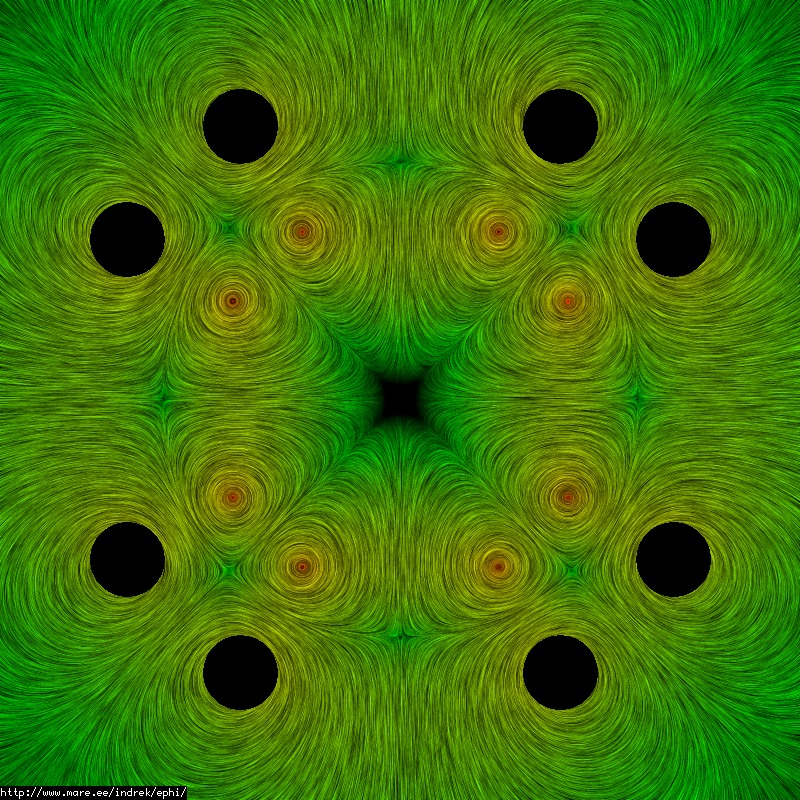
The point being that no field lines intercept the vessel? True, but particles that are on field lines sufficiently close to the field null will have a good chance of hitting the wall due to the excursion of their gyro-orbit. It's still cusp confinement, just in reverse. Your idea of a second set of coils might be part of a solution, but it's still not clear to me whether there is a topological solution or not. (BTW, the picture was a big help.)kcdodd wrote:Like I said in the other thread, putting mirror coils outside the maggrid will ensure a boundary for the maggrid field inside the chamber if it is required. It's just like the image solution used earlier to find approximate wiffleball field, except the maggrid would be the inner coil and would be real not an image.