Hopefully Nebel's team has enough data on electron confinement to say definitively that wiffle-ball trapping works, regardless of theory.I was planning to take this up with Dr. Nebel directly, but since there seems to be so much interest at a reasonable technical level, I'll give it a go here.
About that whiffle ball. It seems the picture is a spherical region with a fairly sharp transition from being field-free inside to being plasma-free outside. Clearly, the field must be parallel to the spherical surface nearly everywhere and, equally clearly, it can't be parallel absolutely everywhere. That's why the whiffle ball needs holes (cusps), although they may be very small.
Two cusps would be fine with me. Then it would be a sort of mirror machine (presumably axially symmetric). But the polywell is supposed to have 14 holes (6 faces plus 8 corners). I believe there is topologically no way to do this (with some exceptions that don't seem relevant) without having points on the surface where the field vanishes. In addition to the cusps, where the field converges and then takes a dive, there must be points where the field lines in the neighborhood are hyperbolic.
If you think I'm wrong, just try to draw a picture of the field lines around 4 or 5 of those whiffle ball holes.
Carlson and Nebel
Maybe Indrek can address this Carlson objection:
Nebel answers thus:
More from Carlson:
He also says this:
The peak fields for the reactor designs (at least for our reactor designs) are in the 5-10 T range. however, these are work in progress.
...
I don't know exactly what to say, but we have run Gauss meters all over the face of the cubes and through the corners and we don't see any low field regions. The fields peak near the conductors and fall off near the coil centers, as you would expect. If you can identify where you think the field will vanish, we can measure it and see next time we break vacuum.
More from Carlson:
I'm not sure whether he's taking into account the "pushback" of the electrons on the magnetic field.Taking a magnetic field of 8 T and a (perpendicular) deuteron energy of 100 keV, I get a gyroradius of 8 mm. In a machine of radius 1.5 to 2 m, the ions will be highly magnetized. Is this now considered unimportant? What about Krall's calculation of the deflection of an ion falling in to the center?
Taking again 8 T and adding the assumption of a high beta plasma with T = 100 keV (perhaps being sloppy with factors on the order of unity), I get a density of 1.6e23 m^-3, and a Debye length of 6 nm. That suggests to me that the plasma strongly fulfills quasi-neutrality, so that it is a dangerous proposition to consider electron and ion transport separately. An MHD picture would be more appropriate, like in a tokamak.
He also says this:
It sounded to me like they measured and they fall but don't vanish there. Does theory predict that they would?"The fields peak near the conductors and fall off near the coil centers, as you would expect."
I am making two claims.
(1) The field must be radial at the midpoints of the sides of the cube. I assume you either see this or haven't checked yet. I believe that the field will be smaller there than at the corners, in which case these points will be more important for electrons losses than the corners. What relative field strengths are actually observed?
(2) The picture of a wiffle ball cannot be accurate. "Whiffle ball" suggests a spherical, high-beta plasma, surrounded by a low beta magnetic field, with the exception of a small number of "holes" where the field lines converge and become radial. But what happens at the midpoints of the sides of the cubes? The tangential field must vanish by symmetry, so they can be neither part of the solid ball, nor can they be holes.
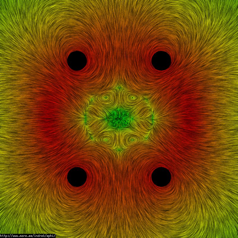
Using Vizimag (2D only) I made a polywell equivalent. The field vectors are thus:-

and the field intensity is thus:-

As far as I understand, the field vectors indicate the direction an electron might experience force upon itself if it were at a particular point; and the intensity indicates the magnitude or size of that force. Thus, there are point (or perhaps short line) cusps, but no regions of zero magnitude.
Regards,
Tony Barry
and the field intensity is thus:-
As far as I understand, the field vectors indicate the direction an electron might experience force upon itself if it were at a particular point; and the intensity indicates the magnitude or size of that force. Thus, there are point (or perhaps short line) cusps, but no regions of zero magnitude.
Regards,
Tony Barry
At first I couldn't figure out what Carlson was talking about because I thought he meant the middle of each coil, but then I realized he probably just means the cusps at the center of each square. Bussard didn't seem to think those were any different than the other (corner) cusps, I'm not sure why Carlson does.
Ah, here we go:
So they are a little different, but they're actually better (i.e. smaller leaks).In any realistic device, the effective overall trapping factor is
reduced from the pure WB mode by circulation through the
semi-line-cusps at the spaced corners, which allow much
greater throughflow per unit area than through the point
cusps of the polyhedral faces.
Nice pictures. Just about what I have, except mine are in 3D so a tad different.tonybarry wrote:Using Vizimag (2D only) I made a polywell equivalent. The field vectors are thus:-
As far as I understand, the field vectors indicate the direction an electron might experience force upon itself if it were at a particular point; and the intensity indicates the magnitude or size of that force. Thus, there are point (or perhaps short line) cusps, but no regions of zero magnitude.
Regards,
Tony Barry
The lines on that picture are actually the b-field lines. An electron would experience the Lorentz force F=q*(v x B) - where v x B is the cross product between the electron speed (v) and the b-field line (B). A cross product gives you a direction perpendicular to both the speed vector and the field line. So an electron exiting a cusp would rotate around the field lines (as the force they experience is always perpendicular to the field lines).
As for commenting on the wiffleball - I don't have much insight here. My simulations never showed "zero" field inside the wiffleball. The best picture of a "ball" I have is this:
Here you can see the topology of the field lines at the faces and at corners (2 faces, 4 corners in this cut). The field is indeed zero at the 6+8 exit points.
But this ball shape in my simulation was not stable, and my simulation was broken in many other ways as well, so I wouldn't put much trust in this at all.
- Indrek
^ Hey Indrek, nice to see you back. I was just about to post up that same pic, lol. It really does a great job of explaining beta conditions.
Nice one Dave. I was trying to understand what Carlson was saying too. It seems he didnt have the full picture about beta=1 and how the main reaction space is free from magnetic influence. Most serious criticism of the machine simply comes from people with misunderstandings of how the machine works. Which is totally fine. Fusion aint easy. I got to hand it to Carlson though, I doubt he has spent as much time studying Polywell as we have.
Still though, Bremstrallung radiation and issues maintaing a non thermal velocity distribution / complex potential well are all excellent points. It seems that he is slowly comming round. It will be interesting to see what he thinks in the long run. We might even see him here.
The dialogue he had with Rostoker and Monkhorst was epic. At the bottom of that link you will find his address.
A. Carlson
Max Planck Institute for Plasma Physics,
85748, Garching, Germany
TallDave wrote:So they are a little different, but they're actually better (i.e. smaller leaks).In any realistic device, the effective overall trapping factor is
reduced from the pure WB mode by circulation through the
semi-line-cusps at the spaced corners, which allow much
greater throughflow per unit area than through the point
cusps of the polyhedral faces.
Nice one Dave. I was trying to understand what Carlson was saying too. It seems he didnt have the full picture about beta=1 and how the main reaction space is free from magnetic influence. Most serious criticism of the machine simply comes from people with misunderstandings of how the machine works. Which is totally fine. Fusion aint easy. I got to hand it to Carlson though, I doubt he has spent as much time studying Polywell as we have.
Still though, Bremstrallung radiation and issues maintaing a non thermal velocity distribution / complex potential well are all excellent points. It seems that he is slowly comming round. It will be interesting to see what he thinks in the long run. We might even see him here.
The dialogue he had with Rostoker and Monkhorst was epic. At the bottom of that link you will find his address.
A. Carlson
Max Planck Institute for Plasma Physics,
85748, Garching, Germany
Purity is Power
Thank you Tom. I started using Vizimag because of a question I couldn't answer out of my own knowledge. That question is kind of dumb, but you know how it is, even the dumb queries can get you hooked.
The thing is, does the magnetic field balloon out the "back" of the polywell (i.e. towards the vacuum containment vessel) ? That is, the polywell fields emanate from each coil individually. If we just switched one coil on, the field would have a certain dispersion pattern towards the centre of the polywell, and a symmetrical pattern out the back. If we then turn on all coils, does the field "out the back" balloon out ... or is the front of the field divorced from the back of the field?
Using Vizimag, I attempted to find the answer. It's counter-intuitive as far as I can see ...

The field strength lines are the same in both cases. The inside line is 2T, then 1T, 0.5T, 0.2T, and finally 0.1T (logarithmic gradients). Note the colour play is an automatically generated gradient and does not correspond to the same field strength in separate images. The coils are 200mm by 40mm, with 2000 turns of 100A. The analysis mesh is 400 x 400 (the finest available in Vizimag).
I would have expected that the field would balloon out the back when the polywell runs in "closed" mode with all coils working. But it appears that the field propagates much further out the sides (top right to bottom left) when two coils are removed.
For one coil vs four coils the effect is even more pronounced:-

This is surprising to me, but I can understand the picture on the EMC2 webpage a lot better because of this. The coils are close to the vacuum tank walls because they can be ...
Regards,
Tony Barry
The thing is, does the magnetic field balloon out the "back" of the polywell (i.e. towards the vacuum containment vessel) ? That is, the polywell fields emanate from each coil individually. If we just switched one coil on, the field would have a certain dispersion pattern towards the centre of the polywell, and a symmetrical pattern out the back. If we then turn on all coils, does the field "out the back" balloon out ... or is the front of the field divorced from the back of the field?
Using Vizimag, I attempted to find the answer. It's counter-intuitive as far as I can see ...
The field strength lines are the same in both cases. The inside line is 2T, then 1T, 0.5T, 0.2T, and finally 0.1T (logarithmic gradients). Note the colour play is an automatically generated gradient and does not correspond to the same field strength in separate images. The coils are 200mm by 40mm, with 2000 turns of 100A. The analysis mesh is 400 x 400 (the finest available in Vizimag).
I would have expected that the field would balloon out the back when the polywell runs in "closed" mode with all coils working. But it appears that the field propagates much further out the sides (top right to bottom left) when two coils are removed.
For one coil vs four coils the effect is even more pronounced:-
This is surprising to me, but I can understand the picture on the EMC2 webpage a lot better because of this. The coils are close to the vacuum tank walls because they can be ...
Regards,
Tony Barry
Last edited by tonybarry on Mon Jun 23, 2008 1:27 pm, edited 1 time in total.
It would be nice to have some kind of blink rate control.
Or else some stationary versions.
BTW A blink rate of 1/2 or 4X (rate) of what you have now would be better. Alternate fast enough that you don't have to remember the previous image or slow enough so you can.
Or else some stationary versions.
BTW A blink rate of 1/2 or 4X (rate) of what you have now would be better. Alternate fast enough that you don't have to remember the previous image or slow enough so you can.
Engineering is the art of making what you want from what you can get at a profit.
It's not counter intuitive at all! Fields add, so with two coils opposite you will see a zero flux region in the center. With two coils at 90 degrees, they add in the center.
In the next couple of weeks I hope to be able to get some 3D views up that people can rotate around on their own machines. Blender has a free viewer, so I only need to make the data file fit what they want.
Seeing the difference between tombo's coils and Bussard's coils and the shaped coils (to help reduce impact cross section) will be very useful.
Then add the E fields. Then add the plasma. It will make "intuition" a whole lot easier!
-
StevePoling
- Posts: 57
- Joined: Fri Jun 13, 2008 8:03 pm
- Location: grand rapids, MI
- Contact:
I'd like to see...
When we have a 3D visualization, I'd like to see what the visualization shows when the grids touch (as in earlier WB machines) just to see what "funny cusps" look like.drmike wrote:...Seeing the difference between tombo's coils and Bussard's coils and the shaped coils (to help reduce impact cross section) will be very useful.
Then add the E fields. Then add the plasma. It will make "intuition" a whole lot easier!