Indrek's plot isn't just impressive, its illuminating! I've begun to get a bit more hope for the Polywell once more.
If you imagine a pellet exploded in the zero-field region of the plasma, or alternatively electrons injected in precisely down the cusp lines then the superconductor approximation is a very good one indeed, at timescales lower than the restive skin time (and I would imagine a 100keV plasma would quite a high restistive skin time). The only difference between a plasma on timescales lower than the resistive skin time and a superconductor is that the superconductor actively expels magnetic fluxlines out of it after it makes the transition from a normal conductor while a plasma, once formed from a gas will keep most of the fluxlines that were inside it during its initial breakdown inside it for ever after.
If said plasma during its initial breakdown from background gas or an exploding pellet, or through and electron beam coming in through precisely its mirror axes, has no magnetic flux lines inside it initially, then to all intents and purposes before a resistive skin time it is a superconducting bag.
I'm pretty sure this assumption applies on the timescales professor nebel is experimenting on, and the configuration could be maintained in steady state *provided* electrons that diffuse into the field are scraped off at low energy and replaced by electrons at the mirror axes at a timescale shorter then the resistive timescale, i.e., the lifetime of the electrons inside the device is less than the resistive timescale.
While I too was pleasantly surprised by Indrek's models, in hindsight I shouldn't have been, in addition I'm pretty sure their correct, given his initial assumption of a spherical wiffleball. On the surface of a superconductor, the magnetic fieldlines can only be parallel to the surface by definition, therefore even if there is a slight parallel component of the field on the surface of the wiffleball would be sufficient to negate any possibility of linecusps existing in that region.
Art:
I suspect that if you plot the shape of the fieldlines at a radius slightly beyond the wiffle ball surface you will, indeed find a large perpendicular component to the sphere that's looks very like a line cusp, however that weak parallel component next to the sphere might be enough to shield the electrons from those pseudo-line cusps that lie beyond (after all, an electron larmor radius isn't very large ) except at the weakest regions of the "funny cusp"
Here's a thought experment:
If you had a superconducting plane with two infinite parallel straight wires you would indeed create a line cusp, in that along a line the the field would be precisely zero, if you then curved those wires way from the plane, then their images diverge aswell, and you get a weak component of the magnetic field pointing along the direction of what was once "the line cusp" this field, though quite weak, may be strong enough to shield the electrons from the pseudo-line cusps that lie beyond.
Regarding recirculation I still say the best you can do is have ions being lost out of the cusp hole, with the negative well seriving to make those cusp holes an electron larmor radius as opposed to an ion larmor radius.
All in all I say the first point of disputation goes to the Polywell!
Possible wiffle-ball analytical solution
-
Art Carlson
- Posts: 794
- Joined: Tue Jun 24, 2008 7:56 am
- Location: Munich, Germany
We agree that in the spherical superconducting model, there are, strictly speaking, no line cusps. On the faces there are 6 simple point cusps, that will still be point cusps when we model the plasma shape more accurately. In addition, at the 8 corners and 12 edges, there are field lines that are purely radial, and therefore show a field null at the surface of the sphere. At these positions, force balance is obviously not satisfied, and a flexible plasma model will bulge at these positions, with as yet unknown consequences for the field topology. We can say that the edges of the cube, even in the spherical model, have some characteristics of a line cusp, in that any field line passing through the edge will end on the surface of the sphere (at the midpoint of an edge).
If the question in dispute is whether the polywell should be expected to have losses scaling like point cusps or like line cusps, you can't fairly say that we have even approximately resolved this point. All we have done - still a major step - is to sharpen the question.
If the question in dispute is whether the polywell should be expected to have losses scaling like point cusps or like line cusps, you can't fairly say that we have even approximately resolved this point. All we have done - still a major step - is to sharpen the question.
OK, thanks.kcdodd wrote:Are you asking about the element currents? They are circular loops of currents inscribed within the triangular elements. I tried line-segment current loops but they didn't work so well though I'm not really sure why, I didn't see anything wrong with the equation. The loops work well for finding the field at the test points but they are not perfect either because they leave gaps in the field between the circles.
Ok, here is my first stab. It's still a bit rough but I think the edge cusps do actually appear to form as the shape comes to equilibrium. So we might have to deal with their existence after all. Unless the bfield makes a sharp turn at the edge that isn't caught in the sim's accuracy.
http://www.andromedaspace.com/files/polyg0001.png
http://www.andromedaspace.com/files/polyg0001.png
Carter
kcdodd: hey, that's a great first cut result ... we're still on track I think.
Did you include for the magnetic surface tension force, i.e. tangential to bag surface as well? Or just a simple balance of normal forces, plasma pressure internal versus magnetic pressure external.
The magnetic tension force is the key question for me, it will be the stabiliser (or destabiliser) of the interface.
It will be something like t dot (B dot grad) B
where t is the unit length surface tangential vector and B the mag. field ... but it is probably direction dependent also since the surface tangent plane is described by two vectors, tangential and bi-normal.... this is where I got hung up on the math. There is a nice clear relationship between the two radii of curvature of the surface and the two unit tangent vectors but I've lost it. The Laplace-Young equation for surface tension has a
http://en.wikipedia.org/wiki/Young%E2%8 ... e_equation
generalisation to direction dependent surface tension and this will be the one we are after. ... great stuff.
I'm wondering how we can just use this equation
http://en.wikipedia.org/wiki/Magnetic_tension_force
at the surface for a neglibly small velocity (i.e. set to zero), and derive a young-laplace generalisation for plasma/vacuum field interface by taking dot products of this with normal, tangent and bi-normal vectors? Cleanly spitting out an analytic expression including the principal (maximum and minimum) radii of the surface curvature .... assuming such geodesics exist.
kc, the resulting shape is like you just poured plaster into the middle of a polywell. I love it.
I have a more general question. When I look @ kc's green bag, I see 3 major features that repeat, the gentle peaked cone, the tri face pinch, and the gently curved ridge. If we had a Dodec the same overall size as WB-7, I'm guessing the resultant topology would have the same features but smaller, and more of them. Partially due to the smaller individual coil size.
So are we then talking about a potential well with considerably less spiky-ness to the spiky bag? The "mean spike size" has gone down using a dodec compared to the truncube, no ?
For some reason I find this just massively profound in respect IIRC, to Bussards saying the dodec should be 3 times better than the truncube. Or am I seeing a relationship where there is none.
I like the p-B11 resonance peak at 50 KV acceleration. In2 years we'll know.
I think there is still a lot to do though. I'm trying to increase the accuracy to get closer to the edges.
It took 22 steps to get to that state, and here are the intermediary steps to see what happens.
P.S. does someone else have an equation for the magnetic field around a finite line segment current?
http://www.andromedaspace.com/files/polyg/polyg0000.png
http://www.andromedaspace.com/files/polyg/polyg0001.png
http://www.andromedaspace.com/files/polyg/polyg0002.png
http://www.andromedaspace.com/files/polyg/polyg0003.png
http://www.andromedaspace.com/files/polyg/polyg0004.png
http://www.andromedaspace.com/files/polyg/polyg0005.png
http://www.andromedaspace.com/files/polyg/polyg0006.png
http://www.andromedaspace.com/files/polyg/polyg0007.png
http://www.andromedaspace.com/files/polyg/polyg0008.png
http://www.andromedaspace.com/files/polyg/polyg0009.png
http://www.andromedaspace.com/files/polyg/polyg0010.png
http://www.andromedaspace.com/files/polyg/polyg0011.png
http://www.andromedaspace.com/files/polyg/polyg0012.png
http://www.andromedaspace.com/files/polyg/polyg0013.png
http://www.andromedaspace.com/files/polyg/polyg0014.png
http://www.andromedaspace.com/files/polyg/polyg0015.png
http://www.andromedaspace.com/files/polyg/polyg0016.png
http://www.andromedaspace.com/files/polyg/polyg0017.png
http://www.andromedaspace.com/files/polyg/polyg0018.png
http://www.andromedaspace.com/files/polyg/polyg0019.png
http://www.andromedaspace.com/files/polyg/polyg0020.png
http://www.andromedaspace.com/files/polyg/polyg0021.png
Carter
You can approximate it with the Biot-Savart Law:kcdodd wrote:P.S. does someone else have an equation for the magnetic field around a finite line segment current?
dB = (u0/4pi)(i*ds X r)/r^3
dB : increment in magnetic field from the segment.
u0 : permeability constant.
i : current.
ds : length and direction of your line segment.
r : vector from the line segment to the point of interest.
X : cross product operator.
Strictly valid if r >> ds. If r is not >> ds, you may have to take an integral along the line segment.
kcdodd:
I've thought a bit more about this tension component and I think the way you've set it up with a mesh of discrete current loops lying upon the surface actually has this term accounted for. Since the momentum equation for small velocities reduces simply to
grad P = JxB
and since the current loops lie tangent to the surface, upon which the B-field is also tangential then the right hand side is by construction a vector normal to the surface (pointing inwards) and the right hand side is just the pressure gradient of the plasma pushing out, also normal to the surface. Bottom line, I'm think that for the current approximations and assumptions (superconducting plasma with image current system lying on the bounding surface) you might have a valid solution.
Edit: hmmm but if you've just balanced field magnitude with pressure on the surface then you may still be missing the n dot (B dot grad) B term from the rhs of the above equation. Can you write-up how you did it?
So now then, the iterative calc. solver that you do is like a small displacement perturbation out to a spherical shape and then let the surface relax back to equilibrium and calc. displacement in time steps, i.e. surface velocity ...... in this vein, perhaps if you added a time varying plasma pressure you could make an illustrative animated gif demonstrating how it pulsates about the equilibrium shape? .... with your back pocket Cray of course:)
How does the equilibrium shape vary for increasing/decreasing plasma pressure??? Does the cusping get more/less pronounced? Big questions.
-
Art Carlson
- Posts: 794
- Joined: Tue Jun 24, 2008 7:56 am
- Location: Munich, Germany
This term vanishes because n dot B vanishes. I'm pretty sure the magnetic tension doesn't affect the force on the plasma.icarus wrote:kcdodd:Edit: hmmm but if you've just balanced field magnitude with pressure on the surface then you may still be missing the n dot (B dot grad) B term from the rhs of the above equation.
I've been playing around with different types of surface currents. It really bugged me why the edge currents around the triangles didn't work when the circular currents did. Maybe the fact that the loops left holes allowed a more local solution, which questions it's validity to me since we don't know what the real magnetic strength is supposed to be, since the vertices (between the loops) didn't meet the conditions.
But now I went to a kind of dipole moment density per area at each vertex. Then you will get currents perpendicular to the gradient in dipole density between each vertex. Using linear gradient its easy to create current line-segments across the face of the triangles. However, now this only solves for fields at the vertices, and the faces no longer have tangential fields.
Indrek can you give the exact parameters of the coils and sphere and magnitudes of field values at the surface from image coils?
Carter
For specific parameters:kcdodd wrote:Indrek can you give the exact parameters of the coils and sphere and magnitudes of field values at the surface from image coils?
Code: Select all
A=0.150000
R=0.150000, S=0.080000, I=200000.000000
iR=0.051787, iS=0.027620, iI=-340380.343468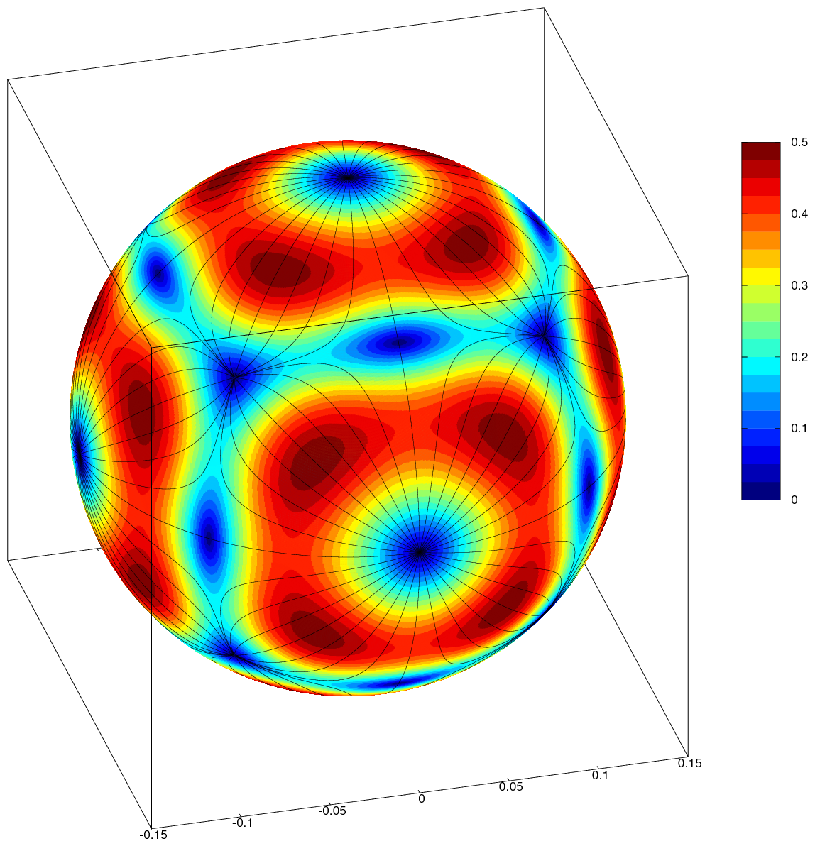
- Indrek