2D WB-7 B-filed simulation

Discuss the technical details of an "open source" community-driven design of a polywell reactor.

Moderators: tonybarry, MSimon

kbaugh
Posts: 22
Joined: Tue Feb 10, 2009 7:10 pm
Location: Fairfax VA

2D WB-7 B-filed simulation

Post by kbaugh »

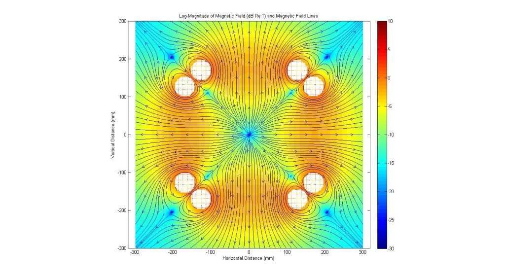
I'm not sure if this isn't old news by now, but here is a quick simulation of the magnetic field in a plane through the center of the WB-7. The "new" bit is that I am showing the magnitude of the B-field on a log scale (decibels re: 1 Tesla), and I am also showing the direction of the B-field components as streamlines (the blue arrows in the image).

Image

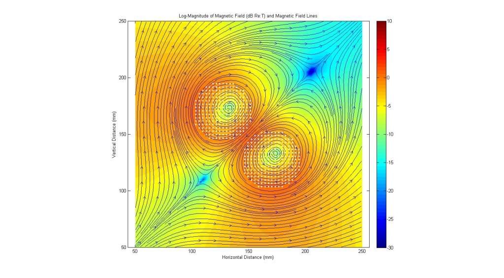
Here is a blow-up of the cusp in the upper right corner. This is at the "funny" cusp where the two grid loops are closest together.

Image

In both images, the white dots are the thin wire loops I was using to compute the field components.

The interesting thing to note is that the streamlines show how the fields generated by the "virtual" loop at the "funny" cusp acts to cancel out the field of the real loops in the immediate vicinity of the cusps, and could act to plug the cusps.

Enjoy!
kbaugh

MSimon
Posts: 14335
Joined: Mon Jul 16, 2007 7:37 pm
Location: Rockford, Illinois
Contact:

Post by MSimon »

How do the field lines close (loop?). Other than around the funny cusp I don't see that.

Perhaps a smaller Polywell in a bigger picture would help.

You might also want to look at some of Indrek's work on field simulations.

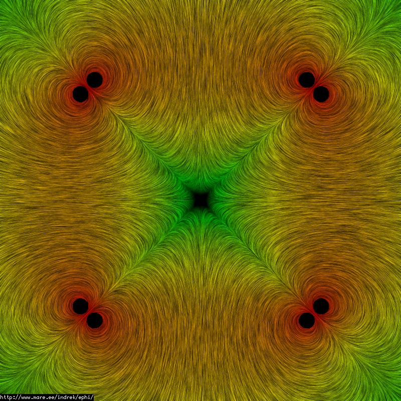
http://www.mare.ee/indrek/ephi/pw2d.html

and especially:

http://www.mare.ee/indrek/ephi/rect_vs_round/
Engineering is the art of making what you want from what you can get at a profit.

tombo
Posts: 334
Joined: Fri May 09, 2008 1:10 am
Location: Washington USA

Post by tombo »

I believe the field lines close through the triangular truncated corner of the cube, which is out of the plane of the picture.
I see two "stagnation points" where the fields seem to cancel (dark blue).
Gyro radius will go very large in those areas.
It would be interesting to see how far those regions extend into and out of the plane of the paper.
Compare them to Indrek's model's results.
Image
Indrek shows those stagnation points or field null regions as being located at the machine center and at infinity.

Welcome kbaugh.
Can you reconcile your model with Indrek's?

My own attempts to model those areas
viewtopic.php?t=599&postdays=0&postorde ... &start=315
Scroll down to July 9, 2009 for the model configuration closest to yours.
I did not plot the cross section that shows those areas, but I don't recall seeing interesting phenomena like that when poking around or I'm sure I would have presented it.
If I can get that model working again I will look for those spots.

Also, the very center of the machine looks, in your model, like a magnetic monopole.
Can you explain that?
-Tom Boydston-
"If we knew what we were doing, it wouldn’t be called research, would it?" ~Albert Einstein

chrismb
Posts: 3161
Joined: Sat Dec 13, 2008 6:00 pm

Post by chrismb »

OK, so obviously neither of these patterns of mag field will work to confine anything, but the design intent is for a WB to form.

Has anyone done a 2D plot of a WB? These plots are irrelevant.

chrismb
Posts: 3161
Joined: Sat Dec 13, 2008 6:00 pm

Post by chrismb »

I guess that around the coils themselves, one needs to control for the size, spacing and current.

Clearly from these pics, that I'd not thought of before, if the 'virtual' coil space where two magrids come close to each other forms a greater magnetic field than that by each coil themselves, then it will 'push' the field back and form nulls.

This would then compromise the flow of both electrons and ions, and cause centre-path hopping in those regions that will cause a large flux straight into the magrid coils.

To avoid this, the field needs to be as per the second one, but I am not sure if you will ever, in practice, avoid getting the field nulls insinde the space where the magrids come close.

If it looks anything like the first, then it clearly won't work.

MSimon
Posts: 14335
Joined: Mon Jul 16, 2007 7:37 pm
Location: Rockford, Illinois
Contact:

Post by MSimon »

Um. chris. The theory is (and I've seen simulations that show) electrons oscillating.

In fact that was Bussard's eureka moment that led to WB-6.

And the "holes" are called cusps. And are well accounted for in the theory (such as it is).
Engineering is the art of making what you want from what you can get at a profit.

chrismb
Posts: 3161
Joined: Sat Dec 13, 2008 6:00 pm

Post by chrismb »

MSimon wrote:Um. chris. The theory is (and I've seen simulations that show) electrons oscillating.
In fact that was Bussard's eureka moment that led to WB-6.
And the "holes" are called cusps. And are well accounted for in the theory (such as it is).
No! The theory is that a magnetic response will be felt in the 'confined electrons' that will lead to a wiffle ball formation.

If the mag fields remain in either of these states, it clearly cannot confine. The cusps cannot be permitted to remain uncontrollled. there will be a flux of plasma up them and that will push the cusps open.

This magnetic field pattern will not remain static. The cusps will either open, which would be the most obvious presumption, or they will close up by the waffleball theory according to the tenuoud assumptions of Polywell adherents.

KitemanSA
Posts: 6180
Joined: Sun Sep 28, 2008 3:05 pm
Location: OlyPen WA

Post by KitemanSA »

First, I agree with Tom, the whole plot looks untenable. There is a monopole that shouldn't be there. The monopole seems to set up a number of nulls that shouldnt be there.

Once that is fixed, then in order to get the wiffleball that Indrek did in another plot, he needs to insert the "image magnet" that Indrek did to mock up the effect of the electrons.

Heath_h49008
Posts: 71
Joined: Wed Jan 27, 2010 9:12 pm
Location: Michigan

Post by Heath_h49008 »

The cusps are never "closed" completely... they are simply not the path of least resistance for the electron. Some will escape and recirculate giving their energy back to the well from which it fled.

chrismb
Posts: 3161
Joined: Sat Dec 13, 2008 6:00 pm

Post by chrismb »

Heath_h49008 wrote:The cusps are never "closed" completely... they are simply not the path of least resistance for the electron. Some will escape and recirculate giving their energy back to the well from which it fled.
Do remember, though, that a magnetic field has an effect on moving charged particles "because" those particles are trying to 'restore' the least energy state, and as you get a flux through the cusps then the cusp fields will change, increasing the entropy (reducing the field). If they didn't then there would be no thermodynamic reason for those charged particles to exit through the cusps.

Unless such a system is excited cyclically, then the fields won't persist dynamically and a 'normalisation' [read 'thermalisation'] will occur in which you would just end up with a 'cold' plasma discharge soup no different to that glowing image on EMC2's home page.

MSimon
Posts: 14335
Joined: Mon Jul 16, 2007 7:37 pm
Location: Rockford, Illinois
Contact:

Post by MSimon »

Simulations I have seen show electrons plugging the cusps. This causes problems for ion injection. Which I think are solvable.
Engineering is the art of making what you want from what you can get at a profit.

tombo
Posts: 334
Joined: Fri May 09, 2008 1:10 am
Location: Washington USA

Post by tombo »

Slicing my B field in the plane being discussed shows a result much like Indrek's.
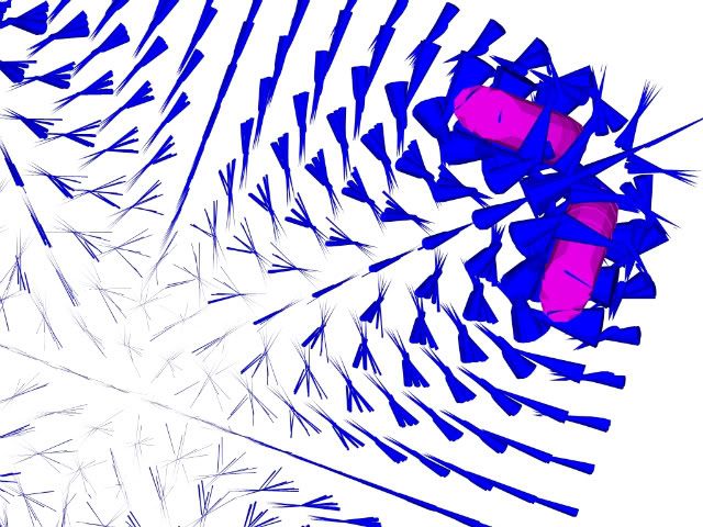
You are looking at 7 layers of B field vectors. The pink shows the coils. The blue cones are B vectors. The wiffle ball center is in the lower left quadrant.
Image
Both the north in and the north out vectors go all the way to the center.
They meet the MHD field stability requirement that "all B field curvatures must be convex toward the higher pressure plasma."
kbaugh's model does not seem to show that and would lead to severe instabilities.
If it is true is could be a show stopper.
This is of course the field without plasma.
It would be deformed as the plasma ball expands in the center of the device creating the wiffle ball.
-Tom Boydston-
"If we knew what we were doing, it wouldn’t be called research, would it?" ~Albert Einstein

kbaugh
Posts: 22
Joined: Tue Feb 10, 2009 7:10 pm
Location: Fairfax VA

Post by kbaugh »

Hmmm.
Obviously, this isn't as clear-cut as I thought. First, this simulation implements an analytic expression for the off-axis magnetic field of a thin current loop using elliptic functions. Each of the six loops is modeled as a set of loops to form the magrids, and the resulting fields (in the 2D plane of regard) are obtained by a linear superposition ("summing up") of the individual field vector components.
(Ref: http://www.netdenizen.com/emagnet/offax ... ffaxis.htm for the expression for the off-axis field vectors)

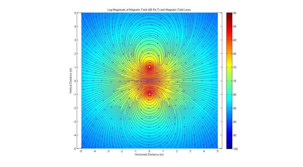
My first concern is to make sure that the analytic model for the thin loops is correct. Here is a test plot of a one-meter radius loop carrying one Ampere of current. The loop is centered at the X-axis, and current flows so that the B-field points in the x direction.
Image

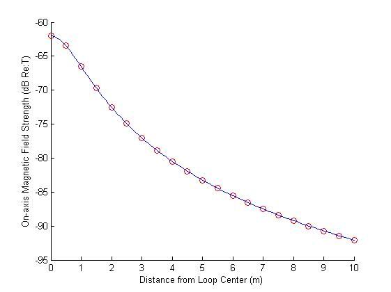
The streamlines look about right, so now I need to check that the magnitude is correct. For this, I compute the field strength on the x-axis, and use the well-known result for the on-axis field strength of a current loop. The plot is shown below.
Image

The blue line is the analytic result using the off-axis code, and the red circles are the results using the on-axis equation. The strength is shown in decibels re: one Tesla. It looks like the magnitude of the simulation code is about right, too.

So, now the question is: does it make any sense that a "stagnation point" would show up in the model just inside of the "funny" cusp?

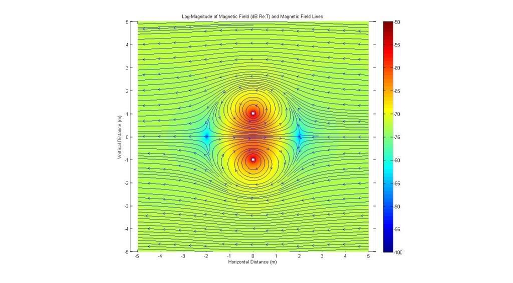
Here is an example of a null field using the same one-meter/one-ampere loop earlier. Here I have added a horizontal B-field that is exacly equal
and opposite to the loop field at +/- 2m.

Image

Note that the field goes to zero (as expected) at +/- 2m, and that the field forms something of a "bubble" around the loop. This happens because the horizontal field is stronger than the loop field at distances beyond 2m, but the loop field dominates at distances less than 2m. Nothing too unexpected if we think about the vector addition of the individual field components.

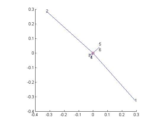
So what happens with the field components at the "stagnation point" just inside the upper-right-hand corner of the original plot? Here is a representation of the six individual B-field vectors:

Image

In the figure above, the blue lines represent the B-field vectors (linear magnitude and direction) for the six grids. The numbers at the end of each line indicate which grid produced which vector. "1" is the vertical grid on the right, "2" is the top horizontal grid, "3" is the vertical grid on the left, "4" is the bottom grid, and "5" and "6" are the out-of-plane grids above and below the 2D analysis plane. The red circle at the center represents the vector sum of those six components, and is indeed very close to zero. If you spend some time pondering this plot and thinking about how the field lines form around each individual loop, it seems to make sense that there could be a cancellation of the field at a point just inside the "funny" cusp.
MSimon
Posts: 14335
Joined: Mon Jul 16, 2007 7:37 pm
Location: Rockford, Illinois
Contact:

Post by MSimon »

It would be interesting to shrink the presentation to show how the field lines close far from the field generator.
Engineering is the art of making what you want from what you can get at a profit.

kbaugh
Posts: 22
Joined: Tue Feb 10, 2009 7:10 pm
Location: Fairfax VA

Post by kbaugh »

msimon -

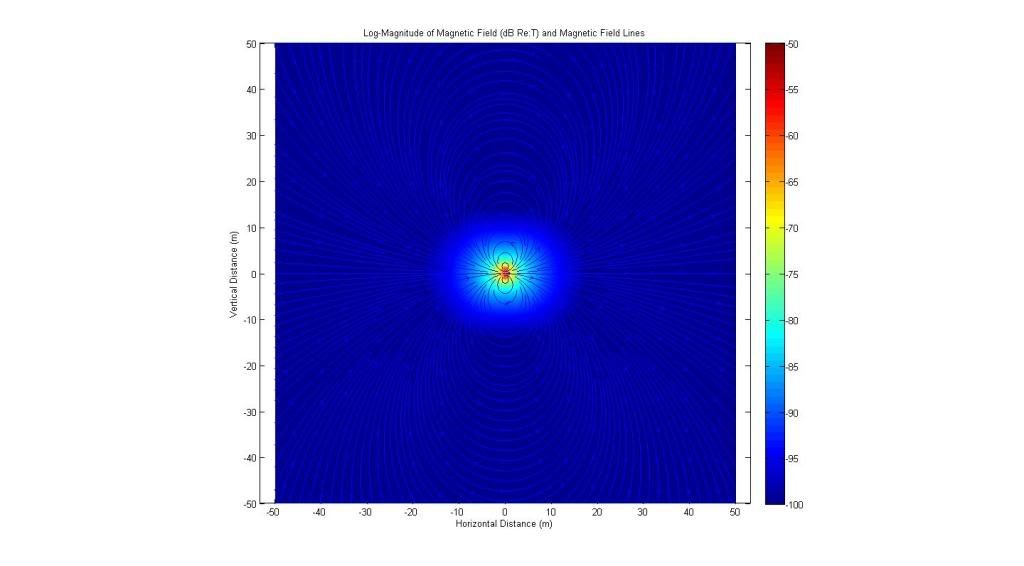
There's several ways to answer this one. First, here is what happens on a single loop at a large distance:

Image

The field lines close (just like in a textbook).

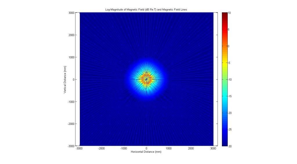
Here is the 2D sim of the WB-7 an a large plane:

Image

The field lines are radial in all directions. Must be a broken simulation, right?

Let's think about this result for a moment. At distances much larger than the loop radius, there is a well-known approximation for the field components. Define a circular coodinate system as the radial distance from the center of the loop, and an angle, theta, measured from the loop axis. The field components are proportional to:

radial: 2cos(theta)
theta: sin(theta)

For the WB configuration (if I ignore the two out-of-plane loops), the approximation becomes:

radial: 2cos(theta) + 2cos(theta-pi/2) + 2cos(theta-pi) + 2cos(theta-3pi/2)
theta: sin(theta) + sin(theta-pi/2) + sin(theta-pi) + sin(theta-3pi/2)

Simplifying,

radial: 2cos(theta) + 2sin(theta) + 2cos(theta) - 2sin(theta) = 4cos(theta)
theta: sin(theta) - cos(theta) - sin(theta) + cos(theta) = 0

In other words, at distances much greater than the loop radius, the total B-field of a WB grid system should be purely radial.

Post Reply