Coil faces.KitemanSA wrote: There needs to be an even number of faces at each vertex, alternating half in and half out.
A question about higher order polyhedra.
You have to wonder why the WB-7 had no faces pointing out (aside from the difficulty of half).KitemanSA wrote:Nope. There needs to be an even number of faces at each vertex, alternating half in and half out.Roger wrote:I cant place it, but something about 3 faces at each vertices seems important.KitemanSA wrote: 4, 6, 8, 12, or 20
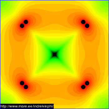
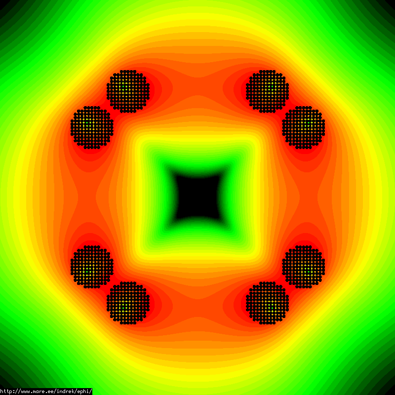
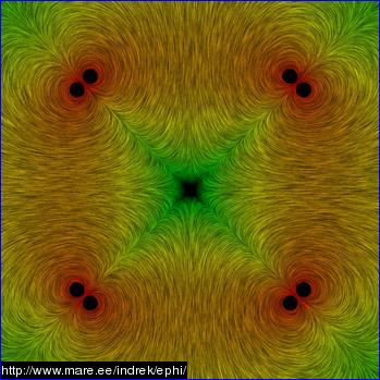
Note that any in faces will cause a non-zero field in the center if the rest of the faces (or even half) are out. The reason for all N faces in three dimensions is the same for all N faces in one dimension (well actually two) . In the center between the two N faces the field is zero. Zero field is essential for device operation.
Look at Indrek's simulations again.
Engineering is the art of making what you want from what you can get at a profit.
Putting aside the fact that the WB6/7 was not the true polywell that DrB wanted, and forgiving the linearization of the funny cusp, the WB6/7 had 8 out faces for the 6 in faces. The virtual faces were out if the reals were in.MSimon wrote:You have to wonder why the WB-7 had no faces pointing out (aside from the difficulty of half).KitemanSA wrote:Nope. There needs to be an even number of faces at each vertex, alternating half in and half out.Roger wrote:I cant place it, but something about 3 faces at each vertices seems important.
Note that any in faces will cause a non-zero field in the center if the rest of the faces (or even half) are out. The reason for all N faces in three dimensions is the same for all N faces in one dimension (well actually two) . In the center between the two N faces the field is zero. Zero field is essential for device operation.
Look at Indrek's simulations again.
Regarding non-zero in the middle, again you are mistaken. As long as the system as a whole has a balance of in vs out, there the "N" vectors meet and cancel in the middle, there will be a null field there. And ALL polywells described above will cancel in the middle.
-
ravingdave
- Posts: 650
- Joined: Wed Jun 27, 2007 2:41 am
Yup. I found the forum and made contact with someone who is in contact with James Woodward. I'm trying to get up to speed on the latest info, and I might actually try to replicate some of their experiments. Compared to Polywell, Mach effect devices are a lot cheaper to build.93143 wrote:ravingdave wrote:Is anybody out there looking at validating or disproving the "Mach Effect?"Yep. Latest news was that Woodward had set up a device that was designed to clearly show the Mach effect rather than generate thrust, and it supposedly showed an effect in antiphase to electrostriction, with S/N of about 10 dB. The claim is that no predicted effect, besides the Mach effect, can explain this result.Betruger wrote:I haven't checked in a while, but last I saw, it was reported as still being worked on at the nasaspaceflight forum. Probably in the Advanced Concepts subforum.
Unfortunately I haven't looked into the matter closely, being somewhat busy with more conventional rocket science...
Thanks for the info.
David
Not so. It shortens the effective length of the linerarized funny cusp so that it better approximates DrB's point like funny cusp, and leaves the N out point cusp as it was. The N in point cusps also remain point-like.MSimon wrote: It would amount to a greatly expanded funny cusp with a lower and more diffuse field over most of the cusp. Not good.
Sorry, is this a game to you? Are you trying to be obstruse? Nowhere did I suggest that we could eliminate some of the face magnets on a cuboctahedron. I did state that there are both in faces (real) and out faces (virtual) on the WB 6/7. I also stated that the real faces could either be 6 in number on on the square faces of the cuboctahedron or 8 in number and be on the triangular faces of the cuboctahedron. I also stated that with the pure octahedron, (the only, I repeat, the ONLY Platonic solid I know this works with) it is possible to have 8 identical real faces of alternating polarity or 4 real and 4 virtual, also alternating, faces. How does that equate to removing one of the magnets on the WB6/7. It doesn't. Pleaase don't put absurd words into my mouth.MSimon wrote:Look at some of Indrek's field simulations and then imagine what they would look like with one face missing.
Putting aside the fact that the WB6/7 was not the true polywell that DrB wanted, and forgiving the linearization of the funny cusp, the WB6/7 had 8 out faces for the 6 in faces. The virtual faces were out if the reals were in.
OK I get your point.
The deal is you want to compress the out faces as much as possible. Leaving an in face out of the system does not do this.
Engineering is the art of making what you want from what you can get at a profit.
Why do you think I want to compress the out faces as much as possible? Makes no sense to me. The ins and outs should be relatively balanced, and situated such that the electron (plasma?) pressure can squeeze off the in and out point cusps as much as possible. Also, to the degree possible, eliminate the line cusps and make sure there is no metal in the way of the funny cusps. But this is going far afield of the lower and higher order polyhedra.MSimon wrote:Putting aside the fact that the WB6/7 was not the true polywell that DrB wanted, and forgiving the linearization of the funny cusp, the WB6/7 had 8 out faces for the 6 in faces. The virtual faces were out if the reals were in.
OK I get your point.
The deal is you want to compress the out faces as much as possible. Leaving an in face out of the system does not do this.
Broaden the N faces narrow the virtual S faces.KitemanSA wrote:Why do you think I want to compress the out faces as much as possible? Makes no sense to me. The ins and outs should be relatively balanced, and situated such that the electron (plasma?) pressure can squeeze off the in and out point cusps as much as possible. Also, to the degree possible, eliminate the line cusps and make sure there is no metal in the way of the funny cusps. But this is going far afield of the lower and higher order polyhedra.MSimon wrote:Putting aside the fact that the WB6/7 was not the true polywell that DrB wanted, and forgiving the linearization of the funny cusp, the WB6/7 had 8 out faces for the 6 in faces. The virtual faces were out if the reals were in.
OK I get your point.
The deal is you want to compress the out faces as much as possible. Leaving an in face out of the system does not do this.
Engineering is the art of making what you want from what you can get at a profit.
Why??? Do that and you lengthen the line cusps and weaken the overall field. What good is that? What DrB wanted to do, in effect, was narrow the real N face by making it square rather than round and broaden the virtual S face by making it from a concave triangle to a straight triangle. Exactly the opposite of what you seem to want to do.MSimon wrote:Broaden the N faces narrow the virtual S faces.KitemanSA wrote:Why do you think I want to compress the out faces as much as possible? Makes no sense to me. The ins and outs should be relatively balanced, and situated such that the electron (plasma?) pressure can squeeze off the in and out point cusps as much as possible. Also, to the degree possible, eliminate the line cusps and make sure there is no metal in the way of the funny cusps. But this is going far afield of the lower and higher order polyhedra.MSimon wrote: OK I get your point.
The deal is you want to compress the out faces as much as possible. Leaving an in face out of the system does not do this.
The logical extension of what you have been proposing is to make square plan form magnets and attach three of them at each vertex of a cube, not a rectified cube, but a cube. I don't think that will work. It would have a VERY long accumulation of line cusps. Not good.
Actually, he conveyed that the coil cans for adjacent equal polarity magnets needed to be 6-8 gyro-radii. He also seemed to want that length where they are adjacent to be a short as possible. This falls out from the square plan-form magnets he wanted, at least to test.MSimon wrote:Dr. B says adjacent faces need to be 6 to 8 gyroradii apart.
You know that is not how I see it. Once you go with a scheme like that the fields are no longer conformal to the grids. Which is why the 6 to 8 gyro radius separation.The logical extension of what you have been proposing is to make square plan form magnets and attach three of them at each vertex of a cube, not a rectified cube, but a cube. I don't think that will work. It would have a VERY long accumulation of line cusps. Not good.
Minimize the area of the S poles (virtual magnets) maximize the areas of the real (N face) magnets. This also has the advantage of making the S poles stronger minimizing leakage through them.
I really wish I had a simulator to see if what happens in my mind conforms to reality.
Feynman said that magnetism and inductance are some of the hardest things to visualize (next to quantum mechanics). And he made his career on visualization. It has served me well too when I see current distributions on PC boards. Very handy when it come to minimizing voltage variations (or minimizing their effect) in grounds in a circuit.
I'm hoping to get a simulator in the near future to settle the question.
So in the mean time we can agree to disagree.
Engineering is the art of making what you want from what you can get at a profit.
Let me add that I have been studying electronics for nearly fifty years and it is only in the last ten or so years that I have gotten a feel for inductance and magnetic fields. Let me repeat: Feynman says that magnetism is tough.
Engineering is the art of making what you want from what you can get at a profit.