A question about higher order polyhedra.

Discuss the technical details of an "open source" community-driven design of a polywell reactor.

Moderators: tonybarry, MSimon

Post Reply
KitemanSA
Posts: 6179
Joined: Sun Sep 28, 2008 3:05 pm
Location: OlyPen WA

Post by KitemanSA »

MSimon wrote: Minimize the area of the S poles (virtual magnets) maximize the areas of the real (N face) magnets. This also has the advantage of making the S poles stronger minimizing leakage through them.
It sounds like you are confusing S poles with cusps. Electrons don't leak out "S" poles, they leak out cusps; S pole and N pole point cusps less that line cusps, but the cusps none the less. By making the S pole face smaller, you by simple geometry are making the line cusps longer. This is NOT what we want.
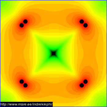
Just to make sure we are talking the same language, you posted this graphic by Indrek (pretty!)
Image
From your subsequent discussion is sounds like you think the dark red area between the pairs of closely spaced dots is the S pole. If so, that may be the problem with our discussion. That is a line cusp, not not a S pole. Regarding a line cusp, you want as small as possible, lengthwise especially. As you pointed out, they need to be ~6-8 gyro-radii wide.

MSimon
Posts: 14335
Joined: Mon Jul 16, 2007 7:37 pm
Location: Rockford, Illinois
Contact:

Post by MSimon »

I'm not confusing S poles with cusps. It is just a convention I use. Real magnets are N poles facing in. The rest follows.

It could just as well be the opposite but that is the convention I have been using here for several years.

If the faces are N poles then the cusps have to be S poles by geometry. Why? Well the field lines point in the opposite direction of the faces. This was worked out here about a year or two ago. It took a bit to convince me. What did the trick was imagining a compass as it traverses around a current carrying wire. If the faces are N the cusps (line and point) are S.
Engineering is the art of making what you want from what you can get at a profit.

KitemanSA
Posts: 6179
Joined: Sun Sep 28, 2008 3:05 pm
Location: OlyPen WA

Post by KitemanSA »

NOTE: All discussion here assumes a WB 6/7 type configuration.
MSimon wrote: I'm not confusing S poles with cusps. It is just a convention I use. Real magnets are N poles facing in. The rest follows.

It could just as well be the opposite but that is the convention I have been using here for several years.
That direction convention is fine with me, I just call the point cusp in the middle of the WHOLE face the pole. The line cusp between pairs of real magnets may have a south in field but is not a south POLE. Since the line cusps are more leaky than point cusps, DrB's desire seemed to be that he wanted to shorten the line-like cusp between real magnets and make the south FACE larger, not smaller.
MSimon wrote:If the faces are N poles then the cusps have to be S poles by geometry. Why? Well the field lines point in the opposite direction of the faces. This was worked out here about a year or two ago. It took a bit to convince me. What did the trick was imagining a compass as it traverses around a current carrying wire. If the faces are N the cusps (line and point) are S.
As I stated above, I am fully aware that the field in the line-like cusp is of opposite polarity to the magnets it runs between. I just disagree that it is the pole. And I disagree that wanting to minimize the line-like cusp equates to wanting to make the south FACE smaller. To minimize the line like cusp, you actually need to make the south FACE larger and the real magnets smaller.

Art C seems to think that this would introduce new line like cusps within the squared up real magnets, but DrB wanted to try it so I think he may have disagreed.

MSimon
Posts: 14335
Joined: Mon Jul 16, 2007 7:37 pm
Location: Rockford, Illinois
Contact:

Post by MSimon »

If the field line direction is what makes the face poles then the cusps are poles as well.
Engineering is the art of making what you want from what you can get at a profit.

KitemanSA
Posts: 6179
Joined: Sun Sep 28, 2008 3:05 pm
Location: OlyPen WA

Post by KitemanSA »

MSimon wrote:If the field line direction is what makes the face poles then the cusps are poles as well.
The field line direction does not make the pole.

Observing a simple stand alone toroidal magnet, the pole (N to S) runs through the center of the face of the magnet; it is at the axis of rotation of the toroid. When you add 6 of the toroidal magnets together in the WB 6/7 configuration you are presented with 6 round faces that by your convention face N in with 6 poles, one at the center of each face. You are ALSO presented with 8 quasi-triangular faces of S facing in with 8 poles, one thru the center of each of the quasi-triangular faces.

The poles WILL be where the point cusps are, out in the middle of the faces. The line-like cusps on the WB 6/7 configuration are a negative fall out from using toroidal magnets rather than the square plan-form magnets that DrB wanted. They take the place of the NULL field that should be the funny cusp. The line-like cusps are an unwanted leakage path. The poles (point cusps) and funny cusps need to be pinched off as much as possible by the wiffle ball effect.

MSimon
Posts: 14335
Joined: Mon Jul 16, 2007 7:37 pm
Location: Rockford, Illinois
Contact:

Post by MSimon »

When you have a current carrying wire creating a magnetic field the idea of poles is somewhat arbitrary.

What counts is the direction of the field vectors.
Engineering is the art of making what you want from what you can get at a profit.

KitemanSA
Posts: 6179
Joined: Sun Sep 28, 2008 3:05 pm
Location: OlyPen WA

Post by KitemanSA »

MSimon wrote:When you have a current carrying wire creating a magnetic field the idea of poles is somewhat arbitrary.

What counts is the direction of the field vectors.
Fine, but what started this discussion was your post"
4 using the alternating faces of the pure octahedron. (Real/Virtual (R/V))
That will get you an S pole at the "missing" faces (assuming N in). Not good.

You want to shrink the S poles as much as possible.
Which I took exception to. The S pole at the missing face is correct, just as it would have been a S with a real magnet there. I just don't agree that we want to shrink it. We want to balance it as much as possible with the N pole / face / magnetic region / whatever you want to call it. That way you will get maximum wiffleballage (point and funny cusps that can be pinched almost shut and minimized line cusps).

MSimon
Posts: 14335
Joined: Mon Jul 16, 2007 7:37 pm
Location: Rockford, Illinois
Contact:

Post by MSimon »

KitemanSA wrote:
MSimon wrote:When you have a current carrying wire creating a magnetic field the idea of poles is somewhat arbitrary.

What counts is the direction of the field vectors.
Fine, but what started this discussion was your post"
4 using the alternating faces of the pure octahedron. (Real/Virtual (R/V))
That will get you an S pole at the "missing" faces (assuming N in). Not good.

You want to shrink the S poles as much as possible.
Which I took exception to. The S pole at the missing face is correct, just as it would have been a S with a real magnet there. I just don't agree that we want to shrink it. We want to balance it as much as possible with the N pole / face / magnetic region / whatever you want to call it. That way you will get maximum wiffleballage (point and funny cusps that can be pinched almost shut and minimized line cusps).
If that is true why wasn't WB-6 designed that way. You need to maximize the area of the N vectors and minimize the area of the S vectors to get a null in the center. That is critical.
Engineering is the art of making what you want from what you can get at a profit.

KitemanSA
Posts: 6179
Joined: Sun Sep 28, 2008 3:05 pm
Location: OlyPen WA

Post by KitemanSA »

MSimon wrote:If that is true why wasn't WB-6 designed that way. You need to maximize the area of the N vectors and minimize the area of the S vectors to get a null in the center. That is critical.
Simplicity and cost is my thought. Since DrB said he wanted to try a square plan-form magnet and was expecting an improvement, I suspect he did not agree with you.

As to getting a null in the center, that is achievable by any combination of vector additions that result in zero.

Take for example the pure octahedron. Got to wikipedia and download the paper cutout form. Color each alternating face red and blue then fold and assemble. Build 8 identical equilateral triangular magnets with rounded corners. Place the magnets snuggly (coil touching coil but with a smidge of hole at the vertices) to make the reds N in and the blue N out (S in). At the center of the octahedron there will be 4 vectors, one normal to each red face pointing in a line from the center of that face to the center of the ocahedron (i.e. in). Normalize the vector to 1 unit representing the general field contribution of a single magnet at the center. At the center of the octahedron there will also be 4 vectors, one normal to each blue face pointing in a line from the center of the octahedron to the center of that face (i.e. out). Add those vectors together and you get the quantity ZERO. That is a null field. Each of the Polyhedra I mentioned before has a null field in the center. They ALL will work to one degree or another.

Now having said that, it may be that ALL the faces of a pure octahedral implementation will be too big to work well, but that has to do with span between the middles of adjacent magnets, not the ratio of In to Out.

MSimon
Posts: 14335
Joined: Mon Jul 16, 2007 7:37 pm
Location: Rockford, Illinois
Contact:

Post by MSimon »

KitemanSA wrote:
MSimon wrote:If that is true why wasn't WB-6 designed that way. You need to maximize the area of the N vectors and minimize the area of the S vectors to get a null in the center. That is critical.
Simplicity and cost is my thought. Since DrB said he wanted to try a square plan-form magnet and was expecting an improvement, I suspect he did not agree with you.

As to getting a null in the center, that is achievable by any combination of vector additions that result in zero.

Take for example the pure octahedron. Got to wikipedia and download the paper cutout form. Color each alternating face red and blue then fold and assemble. Build 8 identical equilateral triangular magnets with rounded corners. Place the magnets snuggly (coil touching coil but with a smidge of hole at the vertices) to make the reds N in and the blue N out (S in). At the center of the octahedron there will be 4 vectors, one normal to each red face pointing in a line from the center of that face to the center of the ocahedron (i.e. in). Normalize the vector to 1 unit representing the general field contribution of a single magnet at the center. At the center of the octahedron there will also be 4 vectors, one normal to each blue face pointing in a line from the center of the octahedron to the center of that face (i.e. out). Add those vectors together and you get the quantity ZERO. That is a null field. Each of the Polyhedra I mentioned before has a null field in the center. They ALL will work to one degree or another.

Now having said that, it may be that ALL the faces of a pure octahedral implementation will be too big to work well, but that has to do with span between the middles of adjacent magnets, not the ratio of In to Out.
I would expect the fields from adjacent magnets to "short out". I agree that such a short will produce a zero center (or so it seems tonight). But will it adversely affect wiffle ball formation? Or maybe there are mechanical troubles from having adjacent faces attract each other.

I'm sure once net power is proved a lot of such schemes will be tried. At this point I'm hesitant to go too far a field. A false move could create a long term set back.

I also wonder if it will affect the curvature of the field adversely.
Engineering is the art of making what you want from what you can get at a profit.

KitemanSA
Posts: 6179
Joined: Sun Sep 28, 2008 3:05 pm
Location: OlyPen WA

Post by KitemanSA »

MSimon wrote: I would expect the fields from adjacent magnets to "short out". I agree that such a short will produce a zero center (or so it seems tonight). But will it adversely affect wiffle ball formation?
The fields from the in/out magnets short out now. I think it is part and parsel of making the wiffleball. It is that "short out" field path that gets pushed back into the wiffleball.
MSimon wrote:Or maybe there are mechanical troubles from having adjacent faces attract each other.
If there were, they should have shown up already, after all we have both faces now.
MSimon wrote:I'm sure once net power is proved a lot of such schemes will be tried. At this point I'm hesitant to go too far a field. A false move could create a long term set back.
That is why I would like to finish the small scale stuff DrB. wanted to do before venturing TOO far into the big $ stuff. Making a flub by too rigid adherance to simple scaling could create as bad a setback as going too far afield.
MSimon wrote:I also wonder if it will affect the curvature of the field adversely.
That is the "centers too far apart" issue I raised before. I am not convinced one way or the other that a pure octahedron will work as well as the current WB6/7 configuration. I just don't know. I also think there are some potentially simple modifications to the pure octahedron that might help, like bowing the sides of the equilateral triangels so the magnets follow a spherical surface.

There are two small scale experiments I would sorely love to see. First is the bow legged version of DrB's square planform cuboctahedron. Second is a simple or bow legger version of the icosadodecahedron. Same basic scale as the WB6/7, but different shape which should lead to improved sphericity and performance.

MSimon
Posts: 14335
Joined: Mon Jul 16, 2007 7:37 pm
Location: Rockford, Illinois
Contact:

Post by MSimon »

MSimon wrote:
Or maybe there are mechanical troubles from having adjacent faces attract each other.
If there were, they should have shown up already, after all we have both faces now.
I don't think that is correct. In the virtual coil spaces you have S - S - S now. And you see that in the field simulations.

In an octa as you propose the virtual fields would be S - N - S - N. That would also tend to flatten the fields where as the current situation the fields bulge. In the situation you propose the fields would no longer be conformal to the coil cases.
Engineering is the art of making what you want from what you can get at a profit.

MSimon
Posts: 14335
Joined: Mon Jul 16, 2007 7:37 pm
Location: Rockford, Illinois
Contact:

Post by MSimon »

MSimon wrote:
I'm sure once net power is proved a lot of such schemes will be tried. At this point I'm hesitant to go too far a field. A false move could create a long term set back.
That is why I would like to finish the small scale stuff DrB. wanted to do before venturing TOO far into the big $ stuff. Making a flub by too rigid adherance to simple scaling could create as bad a setback as going too far afield.
Most of the big $$ items, vacuum pumping, power supplies, radiation shielding, lab eqpt. etc are the same no matter the coil geometry.

You also need to consider all this from the point of view of an investor. They like continuity. And scaling is best PROVED by sticking to the current geometry. I wouldn't even change to square plan coils until scaling is proved. Plus I can get COTS SC coils in a toroidal configuration. If I go to square plan (triangular plan) a custom winding set up must be designed. This adds cost and time. On top of that the problems of mfg of toroidal coils have been field tested. In at least 10 to 50 MRIs per coil mfg (currently there are about 100 3 T MRIs in the field). This is not the case if a different coil plan is desired.

From my interactions with various possible investors time is of the essence. Even more so than minimizing costs.

Now if I had big bucks I'd build several adjacent shield buildings and run a bunch of experiments in parallel sharing various bits of lab eqpt (100 psi air, chilled water, power supples, etc) between them. But even the $10 to $15 million required for a SC operation is hard to come by. As in not currently available.

In addition I want to go directly from WB-7.1 to WB-1MW.

All this science fair project theory is marvelous. However, there are other considerations. Engineering considerations. And money is a very big engineering consideration. As is time. Because time is money and commercial advantage.
Engineering is the art of making what you want from what you can get at a profit.

Aero
Posts: 1200
Joined: Mon Jun 30, 2008 4:36 am
Location: 92111

Post by Aero »

MSimon - Very well said.
Aero

KitemanSA
Posts: 6179
Joined: Sun Sep 28, 2008 3:05 pm
Location: OlyPen WA

Post by KitemanSA »

MSimon wrote: Most of the big $$ items, vacuum pumping, power supplies, radiation shielding, lab eqpt. etc are the same no matter the coil geometry.
Yup. And it all exists for small scale. At this point, building and testing the small scale units would probably come to a couple hundred $k if other things were going on to pay the overhead. They got ALL the start-up costs and ALL the wages and a brand new unit for $1.8M and I suspect the wages and start-up were the major part of that.
MSimon wrote: You also need to consider all this from the point of view of an investor. They like continuity. And scaling is best PROVED by sticking to the current geometry. I wouldn't even change to square plan coils until scaling is proved. Plus I can get COTS SC coils in a toroidal configuration. If I go to square plan (triangular plan) a custom winding set up must be designed. This adds cost and time. On top of that the problems of mfg of toroidal coils have been field tested. In at least 10 to 50 MRIs per coil mfg (currently there are about 100 3 T MRIs in the field). This is not the case if a different coil plan is desired.
Hmm. Interesting. DrB seems to have thought that scaling WAS already proved and that the other small scale units were to check other issues. Why do we need to prove scaling yet again? DrN seems to want to check out transport issues by what SEEMS to be more small scale tests. Don't know, he may be planning a larger unit.
MSimon wrote: From my interactions with various possible investors time is of the essence. Even more so than minimizing costs.
Then put in a couple hundred $k to do the small scale stuff like DrB wanted and do it in parallel. If time is of the essence, then what better thing to do than to be prepared to say "here is the most cost effective unit we can design given ALL the issues reviewed"?
MSimon wrote: Now if I had big bucks I'd build several adjacent shield buildings and run a bunch of experiments in parallel sharing various bits of lab eqpt (100 psi air, chilled water, power supples, etc) between them. But even the $10 to $15 million required for a SC operation is hard to come by. As in not currently available.
SMALL SCALE, not intermediate. Small scale ride alongs should be cheap. No new infrastructure, just new product.
MSimon wrote: In addition I want to go directly from WB-7.1 to WB-1MW.
DrB wanted to go to WB100 via two more small scale units. I think he was wise, at least with respect to the two more small scale units.
MSimon wrote: All this science fair project theory is marvelous. However, there are other considerations. Engineering considerations. And money is a very big engineering consideration. As is time. Because time is money and commercial advantage.
IBID re small scale in parallel. The infrastructure exists. USE IT!!
Post Reply