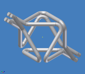
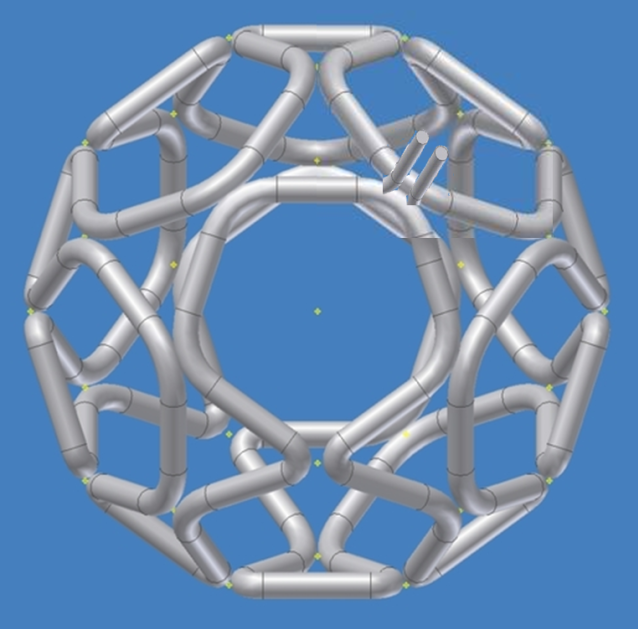
I've seen illustrations like this before, as well as other designs which effectively have one loop serpentining around the entire polywell.tombo wrote:// Pretty Images snipped.
They've always bothered me.
Polywells with traditional coils (like WB-6) use lots of turns to get high B fields with (relatively) low currents. Field strength is proportional to iN, where i is the current and N is the number of turns. So to have a high B, you can have a high i or a high N, or a medium i and N.
For 8" thick coils (ignoring cooling and other effects), to get 1T you are going to need about 160kA-turns. In all of these serpentine designs, I see one turn, which would require 160kA (per T of desired field strength. For a 10T system, that would work out to 1.6MA)
Do the advantages (which have not been specified, as far as I know) of a serpentine design outweigh the engineering challenges of developing a 160kA/T high current power supply?[/i]