BFFOMGFWIWIIUYCTIJSCLTDCUL8TR
I think it translates to: "Oh! Hmm, uhh...cool, bye."
I'll have to ask my daughter to be sure.
Different polyhedra require different strength magnets
I.m not quite sure what you need by way of a sketch.MSimon wrote: How about a sketch?
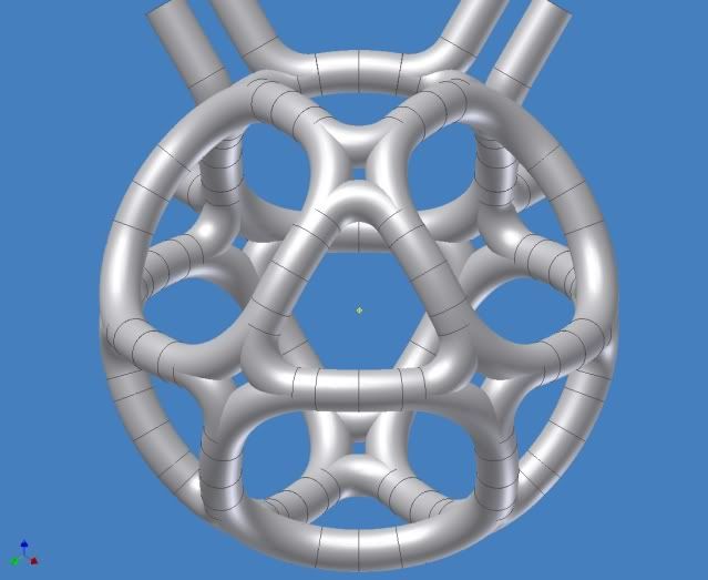
This is a marvelous image that tombo made of the X_MPG. It is a monocoque structure. Tombo's image has one inaccuracy that detracts not at all from the beauty of the thing. The I/O piping doesn't need to be nearly that thick, but forms the only connection needed with the outside. The X_MPGIcos would look similar only it would be icosidodecahedral.
In your mind, strip away the outer casing. Strip away the thermal protection system. Get down to the bare, square cross section of SC that you had been talking about nigh onto a year ago. Now picture that square cross section is made of four strata stacked on top of each other. Each stratum is one winding of an MPG like machine. Each stratum is laid down exactly on top of the prior one, but after all the strata are laid down, the second one out is rotated 90 around the "Z" (blue) axis, the third 180 and the outermost 270. Thus, each side of the "square" and "triangular" coils has all 4 strata, but the sharp curves at the corners only have two each.
In the ASCII sketch below, the dashes and the brackets are the casings of each stratum. The vertical lines are the SC tape. The tape is aligned, like Saturn's rings, with the center of the core (planet). The slinky form of the tape lets it wrap easily around the core (planet) while the thinness of the tape allows the sharp bend (~2cm) at each of the holey X-cusps. Got it?
Code: Select all
------------------------------
[||||||||||||||||||||||||||||]
[||||||||||||||||||||||||||||]
------------------------------
[||||||||||||||||||||||||||||]
[||||||||||||||||||||||||||||]
------------------------------
[||||||||||||||||||||||||||||]
[||||||||||||||||||||||||||||]
------------------------------
[||||||||||||||||||||||||||||]
[||||||||||||||||||||||||||||]
------------------------------
             |
             V
          Inward
Last edited by KitemanSA on Sun Feb 21, 2010 2:30 pm, edited 2 times in total.
Ok, here is what I am thinking:
dodecahedron topology
1 m toroid coils run at 10 T (20 - 25 cm coil thickness, 60 - 50 cm bore, which exceeds msimon's minimum bore of 10 radii from alpha radiation cooling point of view).
inside dodecahedron diameter about 2 m (assumes 6 -8 radii gap between adjacent coils).
Wall supported coils (total of 4 supports for each coil) and all utilities for each coil fished in though the supports (cold and hot cooling water, liquid N and He, SC current feeds).
Cooling water must be de-ionized due to magrid running at 100 kV (redundant conductivity meters with alarms).
I am thinking of two stages of current transformers for supplying each coil's current. First stage would be a standard design CT, second stage would be a SC CT powered by looping through the first CT. The magrid coil circuit would loop through the second stage CT. This set up will help in isolating the magrid from the current power supplies, and the CT's could be located in the vacuum chamber for safety.
Four total supports per coil with integral utilities as follows:
One support would have the cold water supply (for both circuits if there are two circuits).
One support will have the hot water discharge (if there are two discharges then run them in parallel in the same support).
One support will have the cold N and He and incoming and outgoing coil SC leads run adjacent (no net B field).
One support will have the hot N and He.
Thoughts, chuckles?
Counting the days to commercial fusion. It is not that long now.
MSimon seems to dislike the wall braces.mvanwink5 wrote:Wall supported coils (total of 4 supports for each coil) and all utilities for each coil fished in though the supports (cold and hot cooling water, liquid N and He, SC current feeds).
I don't know. He may just be an "anti-porcupinist".MSimon wrote:And then the mechanical design to resist the generated forces. Lits of nubs or a porcupine of braces to the walls.
I must confess, I am tinged with that dreaded disease. I vastly prefer the monocoque X-cusp system. It has the ABSOLUTE minimum by way of unprotected metal in any electron's pathway, I think. Please note that the beautiful tombo graphic is "designed" not "engineered". The final dimensions may vary!
I am assuming that the wall supports are not exposed metal. Ceramic bushings can be quite strong. If you observe sometime some 230 kv transmission lines are built with freestanding horizontal line insulators that support quite heavy line loads. Further, power conversion grids will have to be supported some way.
To construct a continuous multilayer magrid with no defects and no way to make repairs or do maintenance is a major issue in my mind. Still the design you like is elegant. Perhaps it is easier to build than I imagine.
To construct a continuous multilayer magrid with no defects and no way to make repairs or do maintenance is a major issue in my mind. Still the design you like is elegant. Perhaps it is easier to build than I imagine.
Counting the days to commercial fusion. It is not that long now.
IMO:mvanwink5 wrote:Ok, here is what I am thinking:
dodecahedron topology
1 m toroid coils run at 10 T (20 - 25 cm coil thickness, 60 - 50 cm bore, which exceeds msimon's minimum bore of 10 radii from alpha radiation cooling point of view).
inside dodecahedron diameter about 2 m (assumes 6 -8 radii gap between adjacent coils).
Wall supported coils (total of 4 supports for each coil) and all utilities for each coil fished in though the supports (cold and hot cooling water, liquid N and He, SC current feeds).
Cooling water must be de-ionized due to magrid running at 100 kV (redundant conductivity meters with alarms).
I am thinking of two stages of current transformers for supplying each coil's current. First stage would be a standard design CT, second stage would be a SC CT powered by looping through the first CT. The magrid coil circuit would loop through the second stage CT. This set up will help in isolating the magrid from the current power supplies, and the CT's could be located in the vacuum chamber for safety.
Four total supports per coil with integral utilities as follows:
One support would have the cold water supply (for both circuits if there are two circuits).
One support will have the hot water discharge (if there are two discharges then run them in parallel in the same support).
One support will have the cold N and He and incoming and outgoing coil SC leads run adjacent (no net B field).
One support will have the hot N and He.
Thoughts, chuckles?
All standoffs should have full current so they are magnetically shielded.
Any standoff with SC in it must have all thermal control layers ie. He, LH2, LN2, Cold H2O, Hot H2O, insulation, insulation , insulation
Or if I read you differently: Any standoff with Liquid He in it must have all thermal control layers ie. LH2, LN2, H2O, insulation, insulation , insulation.
Only 3 standoffs per coil are needed for stability, but 5 make for better symmetry. (and for lower mechanical stresses on each)
I don't much like the porcupine look either, but it has modularity going for it.
-Tom Boydston-
"If we knew what we were doing, it wouldn’t be called research, would it?" ~Albert Einstein
"If we knew what we were doing, it wouldn’t be called research, would it?" ~Albert Einstein
I always understood the "funny cusps" to be the same thing as those line-like cusps between the coils where they come the closest to each other.KitemanSA wrote:Actually, this is the definition of the line-like cusp that the WB6 generates in lieu of the funny cusp of the patented design.tombo wrote:The funny cusps are a result of the LOCAL current geometry.
They reside between conductors with oppositely directed currents where those currents come closest together.
Show me the Null Field. I don't see it.If so, and I won't argue the technical validity of your statement, they STILL create a north in/north out pair around the equatorial pipe, which would have a NULL field right through its center and would be the location of electron drain. No?Look at the point at the center of the equatorial segment (center of a set of 4 segments actually). Let's call than 45deg West.
The current flows east above the equator, west on the equator and east below the equator.
This forms 3 triangular coils above the equator and 3 below it around that point.
IN-OUT-IN above the equator
OUT-IN-OUT below the equator
The 2 IN-going coils ABOVE the equator are connected by a narrow neck of IN-going field just ABOVE the center of the equatorial coil quadrant.
The 2 OUT-going coils BELOW the equator are connected by a narrow neck of OUT-going field just BELOW the center of the equatorial coil quadrant.
Those 2 necks are the cusps.
I see that each North region is separated from every South region by at least one current conductor.
i.e. The field only changes direction at a current conductor.
The points closest to the current conductors are the highest B fields in the machine not zero.
Perhaps. It has been a long time since I wrapped my mind around that set of interlocking programs/script files.Maybe not. Maybe the transverse field is sufficient to protect it. Can you tweek my spreadsheet to analyse this?
I got pretty burned out on it. But I may be able to get back to it now, in my "copious spare time."
Perhaps. It has been a long time since I wrapped my mind around that set of interlocking programs/script files.Would be nice. Can you analyze?No GLOBAL effects force the cusps to be on the global equator.
I agree, that area is not as clean as I would like to see it, but I think it works.
Truncated Dodecahedron serpentine coil: I will work on it. It should not be too bad. I first need to reload the programs etc.Let me think about those. I may have a new favorite!The biggest issue with this geometry is the uninterrupted series of cusps located along the 0, 90, 180 and 270 longitude lines.
It looks too much like the original 2-opposed-coil "cusp machine".
It may be interrupted at the poles by tweaking the feed line locations. But that may not be good enough.
The truncube serpentine coil has at least 2 configurations so the trundodecahedron may well also have more than one serpentine solution.
Some configurations are probably nicer than others, either structurally or for symmetry.
-Tom Boydston-
"If we knew what we were doing, it wouldn’t be called research, would it?" ~Albert Einstein
"If we knew what we were doing, it wouldn’t be called research, would it?" ~Albert Einstein
Yes, of course.MSimon wrote:It is not just Amps that count. It is Amp - Turns.All standoffs should have full current so they are magnetically shielded.
To be more precise, the standoffs should have enough current to create a high enough B field at their surfaces to magnetically shield them from the (hopefully somewhat shadowed) plasma environment they live in.
This is hard if the coil has many more turns than the standoff.
It is impossible if there is no current in the standoff. (This was my point.)
If the standoff diameter can be reduced significantly by reduced heat load from residing in a shielded area and by having a reduced SC cross section, then it will have less reduction in surface B field (and in magnetic shielding) compared to the main coils themselves.
Advantage-One pass serpentine coils.
-Tom Boydston-
"If we knew what we were doing, it wouldn’t be called research, would it?" ~Albert Einstein
"If we knew what we were doing, it wouldn’t be called research, would it?" ~Albert Einstein
MMMM, not quite. The "funny cusp" is that point of NULL field where the 4 or more (but even number of) fields meet at a point. The line like cusps are what the APPROXIMATION of the toroidal coils give in lieu of the funny cusps. Same location, different mechanism. The shorter the line-like cusp, the more "funny" it is.tombo wrote: I always understood the "funny cusps" to be the same thing as those line-like cusps between the coils where they come the closest to each other.
Actually, while I was drafting that, I tentatively drew the same conclusion myself. That is why I continued with "Maybe not. Maybe the transverse field is sufficient to protect it. Can you tweek my spreadsheet to analyse this?"Show me the Null Field. I don't see it.
I see that each North region is separated from every South region by at least one current conductor.
i.e. The field only changes direction at a current conductor.
The points closest to the current conductors are the highest B fields in the machine not zero.
God I know how that is. Two 12 hour days last week, along with my more normal 9 hour ones. Praise be to Allah that Monday was a holiday!Perhaps. It has been a long time since I wrapped my mind around that set of interlocking programs/script files.
I got pretty burned out on it. But I may be able to get back to it now, in my "copious spare time."
Yup. Two posted already. Mine (the colorful one) has two even length wings. Not sure that makes any difference except for cooling.Truncated Dodecahedron serpentine coil: I will work on it. It should not be too bad. I first need to reload the programs etc.
The truncube serpentine coil has at least 2 configurations so the trundodecahedron may well also have more than one serpentine solution.
Some configurations are probably nicer than others, either structurally or for symmetry.
Serpentine coils shown above are basically coils with magnetically protected nubs. I am not sure that it is necessary to magnetically protect the nubs at high B fields. But other than that I see no issue with the serpentine magrid as shown above as long as giro radii criteria is met.
Last edited by mvanwink5 on Tue Feb 23, 2010 2:23 pm, edited 1 time in total.
Counting the days to commercial fusion. It is not that long now.
This is my stab at putting some reason to the nubs versus wall supports comparison:
Comparing the cross sections of nubs and wall supports exposed to circulating electrons should take into account the density of the circulating electrons as well as total exposed area. Because the nubs and wall supports can be located where circulating electrons should be low, from that point of view they are comparable. In addition with high B field (I am thinking 10 T), circulating electrons at the location of nubs and wall supports can be close to zero. So, from a circulating electron point of view, the two methods of coil support are comparable (wall mounts have more exposed area but it shouldn't matter).
Positive ions (alpha's) don't circulate, so I am not sure what their path looks like after it clears the magrid. I also don't know if the nubs are that protected in their low electron location. Perhaps the wall supports being located behind the coil makes them more protected, but then I have no idea.
Any thoughts?
Counting the days to commercial fusion. It is not that long now.
Then I suspect you don't understand me correctly.MSimon wrote:Kiteman,
I will reiterate. If I understand you correctly the fields are pointing the wrong way.
Given tombo's graphic I provided several posts ago, the X_MPG, do you think those fields are going the wrong direction? If so, we have an interesting discussion ahead.