magrid design idea

Discuss the technical details of an "open source" community-driven design of a polywell reactor.

Moderators: tonybarry, MSimon

Post Reply
krenshala
Posts: 914
Joined: Wed Jul 16, 2008 4:20 pm
Location: Austin, TX, NorAm, Sol III

magrid design idea

Post by krenshala »

So, I was reading through the thread Different polyhedra require different strength magnets and suddenly got an idea for how to run the magrid. I'm not sure if it is feasible from a B field standpoint, but I don't believe there are problems with running things this way.

Image

The lines leading "out" of the image go to the walls and act as supports. The center "circle" has the same lines leading into the picture for the opposite face, and out of the picture for the near face. If I am correctly understanding the requirements this should create the required fields in the right places.

I'm not sure if doing things this way is silly, or not, but I know it should simplify at least some of the problems with previously proposed idea. Of course, with my luck, it would cause other problems that might be game-breakers.

So, what are the flaws to running the magrid this way?

blaisepascal
Posts: 191
Joined: Thu Jun 05, 2008 3:57 am
Location: Ithaca, NY
Contact:

Re: magrid design idea

Post by blaisepascal »

krenshala wrote: The lines leading "out" of the image go to the walls and act as supports. The center "circle" has the same lines leading into the picture for the opposite face, and out of the picture for the near face. If I am correctly understanding the requirements this should create the required fields in the right places.
My first comment is my standing objection to presented layouts of magrids which don't have obvious loops: To get large magnetic fields you need either high current or lots of windings. If your design doesn't explicitly have loops which winding can be made around, then it need an explanation of how you are going to get lots of windings or an acknowledgement of the need for a high current DC supply.

With that in mind, and assuming that's resolvable, I don't see any particular reason why it wouldn't work. I can make a couple of suggestions for potential improvements:

(A) The supports, as drawn, are not radial from the center. This will (1) potentially expose them to alphas or neutrons streaming from the reaction area (and also shadow any collectors), and (b) potentially require them to handle twisting stresses, not just tension and compression, caused by the plasma pressure within the device. A suggestion would be to mount them radially, in 12 clusters of 4 instead of 24 clusters of 2.

(B) The arcs as drawn follow the contours of the WB-7 coils, which are themselves a compromise to allow for easy coil winding. Preferrably, for minimization of cusps, you'd want the arcs to follow great-circle paths between supports. This would make the circular faces more squareish, and the corners more like triangularish faces, but this is actually closer to the proper geometry.

The astute will notice a problem with (A) which I just realized. The supports will now be in line with the "funny cusps", and recirculation from the funny cusps would be impossible, yielding to high of losses.

I wonder what some of the other experts think of the suggested design.

Heath_h49008
Posts: 71
Joined: Wed Jan 27, 2010 9:12 pm
Location: Michigan

Post by Heath_h49008 »

I'm not an "expert" by any means... but that is not recirculating, the "supports" will direct electrons into the walls, and the open spaces between quadrants on each side would make a "funny cusp" look like a cakewalk to plug.

But, I might be wrong.

krenshala
Posts: 914
Joined: Wed Jul 16, 2008 4:20 pm
Location: Austin, TX, NorAm, Sol III

Re: magrid design idea

Post by krenshala »

blaisepascal wrote:My first comment is my standing objection to presented layouts of magrids which don't have obvious loops: To get large magnetic fields you need either high current or lots of windings. If your design doesn't explicitly have loops which winding can be made around, then it need an explanation of how you are going to get lots of windings or an acknowledgement of the need for a high current DC supply.
I did neglect to include any information beyond the "shape". Did that for simplicity of presentation. My thought was that it would work like the proposed serpentine options.
blaisepascal wrote:With that in mind, and assuming that's resolvable, I don't see any particular reason why it wouldn't work. I can make a couple of suggestions for potential improvements:

(A) The supports, as drawn, are not radial from the center. This will (1) potentially expose them to alphas or neutrons streaming from the reaction area (and also shadow any collectors), and (b) potentially require them to handle twisting stresses, not just tension and compression, caused by the plasma pressure within the device. A suggestion would be to mount them radially, in 12 clusters of 4 instead of 24 clusters of 2.
I was thinking they would actually be radial supports out from the center, or at least staying in the "shadow" of the rings. Again, I was going for simple to see design that people could easily understand.
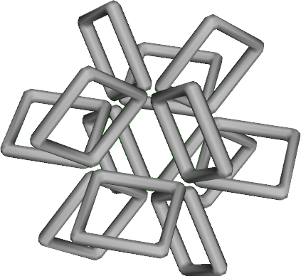
blaisepascal wrote:(B) The arcs as drawn follow the contours of the WB-7 coils, which are themselves a compromise to allow for easy coil winding. Preferrably, for minimization of cusps, you'd want the arcs to follow great-circle paths between supports. This would make the circular faces more squareish, and the corners more like triangularish faces, but this is actually closer to the proper geometry.
Having them form segments of a great circle, or just segments of covering circles, is what I was thinking when I came up with it.
blaisepascal wrote:The astute will notice a problem with (A) which I just realized. The supports will now be in line with the "funny cusps", and recirculation from the funny cusps would be impossible, yielding to high of losses.
My understanding was that the nubs are currently placed where the gaps appear in my drawing. Doing things this way removes the nubs and their subsequent electron losses (and heating). They should also form something more like the corner cusp than the line cusp (with nub) that exists on the WB6/7 design. Also, it should have a virtual coil at those locations, as exists in the corners, if my understanding of the B fields is correct.

As drawn, it needs some obvious improvements (not to mention proper engineering), but thought, if nothing else, it would help spur some more creating thinking. :)
blaisepascal wrote:I wonder what some of the other experts think of the suggested design.

hanelyp
Posts: 2261
Joined: Fri Oct 26, 2007 8:50 pm

Post by hanelyp »

Your proposal sounds similar to something I posted the the big old magrid brainstorming thread.
Image

krenshala
Posts: 914
Joined: Wed Jul 16, 2008 4:20 pm
Location: Austin, TX, NorAm, Sol III

Post by krenshala »

Now that I see the picture (again) I think you're right. It does look very similar to my idea. In fact, your setup looks to me like it would probably work much better than what I envisioned (and did not display clearly in my picture above ;)).

Post Reply