Is There an Optimal Size for Magrid Casings?

Discuss the technical details of an "open source" community-driven design of a polywell reactor.

Moderators: tonybarry, MSimon

Post Reply
KitemanSA
Posts: 6179
Joined: Sun Sep 28, 2008 3:05 pm
Location: OlyPen WA

Post by KitemanSA »

MSimon wrote:It probably has to do with how you saved them. You need more dots.
I did notice that the file type had changed from the .png (portable network graphics) I sent (I think) to a .jpg (IIRC). Could that conversion have reduced it?

Anyway, I think I will just go ahead and get a photobucket account. Thank you for your support.

MSimon
Posts: 14335
Joined: Mon Jul 16, 2007 7:37 pm
Location: Rockford, Illinois
Contact:

Post by MSimon »

KitemanSA wrote:
MSimon wrote:It probably has to do with how you saved them. You need more dots.
I did notice that the file type had changed from the .png (portable network graphics) I sent (I think) to a .jpg (IIRC). Could that conversion have reduced it?

Anyway, I think I will just go ahead and get a photobucket account. Thank you for your support.
Usually it has to do with the format you save it in. I have never had a problem with that conversion before. It is also possible that Photobucket has installed a "new feature" which shrinks oversize files. Check the Photobucket file size vs your file size. Then check their maximum pixel count and framing.
Engineering is the art of making what you want from what you can get at a profit.

Billy Catringer
Posts: 221
Joined: Mon Feb 02, 2009 2:32 pm
Location: Texas

Post by Billy Catringer »

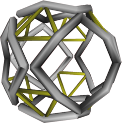
KitemanSA wrote:Please remember that Dr. B had envisioned that the final coils would be either square or pentagonal in plan-form (not cross section, plan-form)with rounded corners. I think this will tend to reduce the overall stresses in the magnet because the coil and virtual coils forces will be better balanced. With the "straight" sides of the coil actually following a "great circle" along the sphere of the well rather than the edges of the cuboctohedron, the primary forces might resolve into simple hoop stresses in most of the magnet.

Need picture! I think I understand, but I need to see a sketch or something before I can say for sure.

I am basing the design of the supporting structure on the fact that copper, like nearly every other known material, becomes about as ductile as a good grade of borosilicate glass once it is at LHe temps. The cores of these things will not tolerate much shear nor will they survive torque loads and vibration will be a big no-no because we are talking about something we will want to seal up and never look at again for twenty years. Besides, I don't think it is a good idea to jiggle and wiggle any magnet producing a 10T field in the presence of conductors of any kind. We'd get currents where we didn't want 'em.

Sadly, support systems get in the way of coolant circulation. This is a tricky business inside and outside the structures supporting the SC cores.

TallDave
Posts: 3140
Joined: Wed Jul 25, 2007 7:12 pm
Contact:

Post by TallDave »

The optimal size is the one Bussard initially proposed: zero.

As of this date, technical issues have prevented this size from being achieved.

KitemanSA
Posts: 6179
Joined: Sun Sep 28, 2008 3:05 pm
Location: OlyPen WA

Post by KitemanSA »

Billy Catringer wrote: Need picture! I think I understand, but I need to see a sketch or something before I can say for sure.
Unfortunately, my sketch shows the same error as
hanelyp wrote:An image I posted to the magrid brainstorming thread:
Image
Same basic config as the cube polywell, but with the coils bent to be more 'spherical'. Is this something like what you're trying to get at?
did here. But if you mentally grow the plan-form till it reaches the edges of the cuboctohedron while making the corners round enough to avoid each other, you almost have it. One step further. The sides of his square plan form have a kink in them. Make them curved to fit the spherical surface and voila!

Billy Catringer
Posts: 221
Joined: Mon Feb 02, 2009 2:32 pm
Location: Texas

Post by Billy Catringer »

A structure like this could be built, but there are several problems with it.

1) How do you wind the coils? If winding coils in this shape is not possible, can a Bitter Plate type of magnet be made in this shape?

2) Assuming one or the other such cores can be made, how do we support it against the stresses that will be applied to it. We want those brittle cores in compression, not tension, shear or torsion.

3) The strands of the SC core contract along their lengths more than they contract in any other direction as they chill. This will put a lot of stress on the strands of the winding no matter what the shape of the core and this shape will likely cause them to develp stresses unevenly.

4) It's necessary to pump lots and lots of cooling water through two separate jackets to keep the heat from reaching the superconducting core. The more twists and turns there are in the way of the water, the more friction there is and there will be an increase in the tendency for the structural system to vibrate. Even without the kinks shown in this sketch, the flow of water will be impeded by the additional turns it will have to make. Vibration is going to be hard to avoid with the simpler toroii.

As far as I can tell, and someone correct me if I am wrong, the SC core will be brittle at LHe temperatures. That means that the support of the SC cores must be as firm and rigid as the foundation of a masonry building. If the structure deforms even a little, the cores will crack or spall and that would lead to a complete failure under load, or the danged things will break sometime during cool down. The entire system will shrink while the two inner coolant loops are filled with LHe and LN2.

KitemanSA
Posts: 6179
Joined: Sun Sep 28, 2008 3:05 pm
Location: OlyPen WA

Post by KitemanSA »

Billy Catringer wrote:A structure like this could be built, but there are several problems with it.

1) How do you wind the coils? If winding coils in this shape is not possible, can a Bitter Plate type of magnet be made in this shape?
I could wind either a standard strand OR quasi-bitter plate magnet in this shape... in copper, and winding with AMSC Gen2 wire would be possible, but a LOT tougher. But assuring appropriate slack or tension to pre-adjust for shrinkage would be much more difficult.
2) Assuming one or the other such cores can be made, how do we support it against the stresses that will be applied to it. We want those brittle cores in compression, not tension, shear or torsion.
If you want them in compression (I suspect you mean you want to squeeze the wires, not push on them) then you would have to transfer the outward loads into a trough which would handle it in tension.
3) The strands of the SC core contract along their lengths more than they contract in any other direction as they chill. This will put a lot of stress on the strands of the winding no matter what the shape of the core and this shape will likely cause them to develp stresses unevenly.
Actually this may be a good thing because it should be easier to wind with a bit of slack than wind with a controlled extra taughtness.
4) It's necessary to pump lots and lots of cooling water through two separate jackets to keep the heat from reaching the superconducting core. The more twists and turns there are in the way of the water, the more friction there is and there will be an increase in the tendency for the structural system to vibrate. Even without the kinks shown in this sketch, the flow of water will be impeded by the additional turns it will have to make. Vibration is going to be hard to avoid with the simpler toroii.
Simple engineering ....ha ha ha ha ha ha ha ha
Personally, I kind of like the idea of using NaK for the first loop. Much lower pressures to deal with at the anticipated temperature. I keep looking for a two phase material that could use the melting process to improve cooling, but...
As far as I can tell, and someone correct me if I am wrong, the SC core will be brittle at LHe temperatures. That means that the support of the SC cores must be as firm and rigid as the foundation of a masonry building. If the structure deforms even a little, the cores will crack or spall and that would lead to a complete failure under load, or the danged things will break sometime during cool down. The entire system will shrink while the two inner coolant loops are filled with LHe and LN2.
Simple engineering ....he he he he ha ha ha
Billy Catringer
Posts: 221
Joined: Mon Feb 02, 2009 2:32 pm
Location: Texas

Post by Billy Catringer »

It's hard to explain what I mean by compression without drawing you the pictures I am working on right now, but I'll try. Because the magnetic array is essentially symmetrical, and all of its elements are symmetrical, the resultants of all the forces acting on them are pushing outwards from the center of the array, acting through the magnetic centers of the the torii. So long as the magnets are powered up, these resultant forces are dominant, gravity counts for very little.

The job of the structure is to counter those resultants while keeping an even load on the SC cores. Strangely enough, this is the easy part. The hard part is accommodating all the other stuff that happens prior to charging while dealing with cool down and then the sudden heating once fusion starts. Shear, torque and tensions stresses have to be kept off the core while all those things are ongoing. Oh, and until the magnets are charged, gravity is a problem. The cores must be trapped so that they do not impose shear stresses on themselvs while fighting gravity.

All of this can be done, but it is expensive. Also, you don't want to overtake the plumbing. It's too easy to plug the drain when ya do tha.

MSimon
Posts: 14335
Joined: Mon Jul 16, 2007 7:37 pm
Location: Rockford, Illinois
Contact:

Post by MSimon »

As far as I can tell, and someone correct me if I am wrong, the SC core will be brittle at LHe temperatures.


MgB helps. The ceramic superconductors not so much.

In any case there are companies with experience in this sort of design. We hire them or hire away one of their designers. Or put out a help wanted ad. The economy may provide some useful talent.
Engineering is the art of making what you want from what you can get at a profit.

MSimon
Posts: 14335
Joined: Mon Jul 16, 2007 7:37 pm
Location: Rockford, Illinois
Contact:

Post by MSimon »

Personally, I kind of like the idea of using NaK for the first loop.
In theory - lots of people like NaK. In practice - not so much.

At this point there is no definite temperature the first shield has to run at. It is only the delta T that is important. All higher Ts get you in an experimental reactor is a smaller radiator.

Power extraction may change that equation. However, there is no reason to make EVERYTHING hard for the experiments.
Engineering is the art of making what you want from what you can get at a profit.

Billy Catringer
Posts: 221
Joined: Mon Feb 02, 2009 2:32 pm
Location: Texas

Post by Billy Catringer »

MSimon wrote:
As far as I can tell, and someone correct me if I am wrong, the SC core will be brittle at LHe temperatures.


MgB helps. The ceramic superconductors not so much.

In any case there are companies with experience in this sort of design. We hire them or hire away one of their designers. Or put out a help wanted ad. The economy may provide some useful talent.

Will definitely need to run everything by the magnet guys first. I thought about trying to talk to them before hand, but if they are anything like all the other folks in engineering specialties, they don't wanna talk to ya until after you slap 'em around with a wad of bills. In all likelihood, the magnet guys make as much money solving your engineering problems as they do selling you their superconducting coils. We'll get our preliminary ideas down and then try to provoke their curiosity. Maybe they'll take the bait.

MSimon
Posts: 14335
Joined: Mon Jul 16, 2007 7:37 pm
Location: Rockford, Illinois
Contact:

Post by MSimon »

they don't wanna talk to ya until after you slap 'em around with a wad of bills.
I have noticed that too. ;-)
Engineering is the art of making what you want from what you can get at a profit.

KitemanSA
Posts: 6179
Joined: Sun Sep 28, 2008 3:05 pm
Location: OlyPen WA

Post by KitemanSA »

MSimon wrote:
Personally, I kind of like the idea of using NaK for the first loop.
In theory - lots of people like NaK. In practice - not so much.

At this point there is no definite temperature the first shield has to run at. It is only the delta T that is important. All higher Ts get you in an experimental reactor is a smaller radiator.

Power extraction may change that equation. However, there is no reason to make EVERYTHING hard for the experiments.
Your list of coolant Ts and flows show the outside coolant loop to by H2O at about 600C, no? Pressurizing that will be a bear, unless you mean steam, and it doesn't carry much heat away. The NaK will allow those temps without the Ps. Just a thouht.

MSimon
Posts: 14335
Joined: Mon Jul 16, 2007 7:37 pm
Location: Rockford, Illinois
Contact:

Post by MSimon »

KitemanSA wrote:
MSimon wrote:
Personally, I kind of like the idea of using NaK for the first loop.
In theory - lots of people like NaK. In practice - not so much.

At this point there is no definite temperature the first shield has to run at. It is only the delta T that is important. All higher Ts get you in an experimental reactor is a smaller radiator.

Power extraction may change that equation. However, there is no reason to make EVERYTHING hard for the experiments.
Your list of coolant Ts and flows show the outside coolant loop to by H2O at about 600C, no? Pressurizing that will be a bear, unless you mean steam, and it doesn't carry much heat away. The NaK will allow those temps without the Ps. Just a thouht.
200C would work just as well for cooling. If the 100C delta T was not a problem at that temp. In fact 50C to 150C (inlet vs outlet) would be fine for a test reactor. There is nothing magic about 600C (at least in the experimental version).
Engineering is the art of making what you want from what you can get at a profit.

KitemanSA
Posts: 6179
Joined: Sun Sep 28, 2008 3:05 pm
Location: OlyPen WA

Post by KitemanSA »

Billy Catringer wrote:It's hard to explain what I mean by compression without drawing you the pictures I am working on right now, but I'll try. Because the magnetic array is essentially symmetrical, and all of its elements are symmetrical, the resultants of all the forces acting on them are pushing outwards from the center of the array, acting through the magnetic centers of the the torii. So long as the magnets are powered up, these resultant forces are dominant, gravity counts for very little.
I said "If you want them in compression (I suspect you mean you want to squeeze the wires, not push on them) then you would have to transfer the outward loads into a trough which would handle it in tension." I presumed you would understand that the trough would be on the outward face of the great-circle parts of the loop. Indeed the main loads will be at the corners of the loops where they must connect across to the next loop (or outward to a strength frame).
The job of the structure is to counter those resultants while keeping an even load on the SC cores. Strangely enough, this is the easy part. The hard part is accommodating all the other stuff that happens prior to charging while dealing with cool down and then the sudden heating once fusion starts. Shear, torque and tensions stresses have to be kept off the core while all those things are ongoing. Oh, and until the magnets are charged, gravity is a problem. The cores must be trapped so that they do not impose shear stresses on themselvs while fighting gravity.
True, all true.
All of this can be done, but it is expensive. Also, you don't want to overtake the plumbing. It's too easy to plug the drain when ya do tha.
Is this in reference to the two phase coolant? Always a hassle, but excellent in concept!

By the way, what sort of loads are we talking about? For a 2m radius machine, 10T, what would be the equivilent pressure?

Post Reply