Is There an Optimal Size for Magrid Casings?

Discuss the technical details of an "open source" community-driven design of a polywell reactor.

Moderators: tonybarry, MSimon

KitemanSA
Posts: 6179
Joined: Sun Sep 28, 2008 3:05 pm
Location: OlyPen WA

Post by KitemanSA »

MSimon wrote:There are line cusps and point cusps. They both matter.
There are point cusps and funny cusps which are quasilinear only in the round plan form coils that DrB did not want. My take is he expected the funny cusps to become much more localized with rounded corner square plan form coils.
MSimon wrote:And then there is the torque on the "V".
Not in mine.

KitemanSA
Posts: 6179
Joined: Sun Sep 28, 2008 3:05 pm
Location: OlyPen WA

Post by KitemanSA »

MSimon wrote:
BUT, many of the benefits like direct, single pass coolant flow,
Direct single pass coolant flow is NOT a benefit. It raises flow rqmts. Or delta T. And it raises delta P. Splitting the flow into six circuits helps.
If it turns out to be a controlling issue, even with the statified counter-flow plumbing suggested, then the individual square plan form coils can be wrapped just as, or even MORE, easily than indicated for the MPG varient. One can STILL make a bowed, square plan form, tensile backbone, Polywell and reap all the benefits.

Billy Catringer
Posts: 221
Joined: Mon Feb 02, 2009 2:32 pm
Location: Texas

Post by Billy Catringer »

This is to scale:

http://www.flickr.com/photos/36049122@N05/3332968375/

As you can see, it is anything but simple.

KitemanSA
Posts: 6179
Joined: Sun Sep 28, 2008 3:05 pm
Location: OlyPen WA

Post by KitemanSA »

Are you trying to do a WB7 size unit with SCs? Your sketch may be proper for that, but given the 29 cm^2 of "engineering" area of SC conductor that MSimon stated was necessary for the WB100, and the ~8in total cross section Tombo claims MSimon stated, the sketch HE made was to scale and the one you made makes no sense. By the bye, the 8" total cross section makes sense given the ~ 8 cm (with coolant channels) needed for the SC core.
Again, another by the bye, I do kind of like his square x-section for the SCs. Makes layup a whole lot easier!

Billy Catringer
Posts: 221
Joined: Mon Feb 02, 2009 2:32 pm
Location: Texas

Post by Billy Catringer »

KitemanSA wrote:Are you trying to do a WB7 size unit with SCs? Your sketch may be proper for that, but given the 29 cm^2 of "engineering" area of SC conductor that MSimon stated was necessary for the WB100, and the ~8in total cross section Tombo claims MSimon stated, the sketch HE made was to scale and the one you made makes no sense. By the bye, the 8" total cross section makes sense given the ~ 8 cm (with coolant channels) needed for the SC core.
Again, another by the bye, I do kind of like his square x-section for the SCs. Makes layup a whole lot easier!


Chikushou! Did I not say that it was to scale? It is to scale! Center line diameter of the SC coil is 2 meters.

(29^2+29^2)^.5 ~= 41cm

That is 41% of the magnet's radius. The first jacket, the one holding the helium, has to have an inside diameter large enough for coolant flow AND supports. The same problem will apply to a magrid of any shape. I used a wall thickness of 12.7mm on all the inner jackets just make sure they do not sag between the internal supports which, I have yet to draw.

There is no way to pull the SC wire through one of these things with a fish tape. All that can be accomplished by such a method is to ruin 5,000 kg or so of superconductor. Each jacket will have to be split into two pieces and welded together after SC layup.

The fabrication of this simple butt-ugly thing is going to be difficult. What do you suppose it will take to do one of those snaky, baseball stitch designs?

As it is, I will have to go to two meter radius instead of one meter. That means much higher costs--on a very simple design.

I have stopped drawing to do a spreadsheet on volumes and weights. I probably should have done that first. If I had, I would have caught this problem before building this rough model. Better a model than metal, I suppose.

krenshala
Posts: 914
Joined: Wed Jul 16, 2008 4:20 pm
Location: Austin, TX, NorAm, Sol III

Post by krenshala »

tombo wrote:The struts are splayed more that I expected them to be in order to keep them in the shadows of the coils. This is not where I would prefer them structurally though.
I wonder if using the dodecahedral configuration would help the placement, structurally, of those supporting members?

krenshala
Posts: 914
Joined: Wed Jul 16, 2008 4:20 pm
Location: Austin, TX, NorAm, Sol III

Post by krenshala »

Billy Catringer wrote:Chikushou! Did I not say that it was to scale? It is to scale! Center line diameter of the SC coil is 2 meters.
If the radius of the device, from core to torii is 2m, how large of a gap are you going to have between individual torus sections if they have a 2m diameter?

KitemanSA
Posts: 6179
Joined: Sun Sep 28, 2008 3:05 pm
Location: OlyPen WA

Post by KitemanSA »

Billy Catringer wrote:
KitemanSA wrote:Are you trying to do a WB7 size unit with SCs? Your sketch may be proper for that, but given the 29 cm^2 of "engineering" area of SC conductor that MSimon stated was necessary for the WB100, and the ~8in total cross section Tombo claims MSimon stated, the sketch HE made was to scale and the one you made makes no sense. By the bye, the 8" total cross section makes sense given the ~ 8 cm (with coolant channels) needed for the SC core.
Again, another by the bye, I do kind of like his square x-section for the SCs. Makes layup a whole lot easier!
Chikushou!
Play nice please.
Billy Catringer wrote:Did I not say that it was to scale? It is to scale! Center line diameter of the SC coil is 2 meters.

(29^2+29^2)^.5 ~= 41cm
Hunh?
Billy Catringer wrote:That is 41% of the magnet's radius. The first jacket, the one holding the helium, has to have an inside diameter large enough for coolant flow AND supports. The same problem will apply to a magrid of any shape. I used a wall thickness of 12.7mm on all the inner jackets just make sure they do not sag between the internal supports which, I have yet to draw.
Maybe I missed it, in truth I have been taking others at their word, but my understanding was that for the 2m radius, full size WB100, the total engineering area of the SCs was 29 cm^2. Multiply that by 2.2 for packing factors and cooling and unknown unknowns, take the square root and that is an 8 cm square for the SCs. Even with a factor of 3.3 for the packing, etc., the square would only be 10 cm. When I the drawing you posted, (not alway accurate) I approximate your square core to be about 29cm on a side. So you read (29cm)^2 and Tombo and I read 29 cm^2. That is a big difference. MSimon, which is it?
Billy Catringer wrote: There is no way to pull the SC wire through one of these things with a fish tape. All that can be accomplished by such a method is to ruin 5,000 kg or so of superconductor. Each jacket will have to be split into two pieces and welded together after SC layup.
Concur.
Billy Catringer wrote:The fabrication of this simple butt-ugly thing is going to be difficult. What do you suppose it will take to do one of those snaky, baseball stitch designs?
Not much. The fixture may take a couple hundred $k to build, but once done, the winding should go easily enough. A cryo-copper fixture would probably be in the low 10s of $k. Less even as a labor of love :wink:
Billy Catringer wrote:As it is, I will have to go to two meter radius instead of one meter. That means much higher costs--on a very simple design.

I have stopped drawing to do a spreadsheet on volumes and weights. I probably should have done that first. If I had, I would have caught this problem before building this rough model. Better a model than metal, I suppose.
Check with MSimon. I think your scale is off.

Billy Catringer
Posts: 221
Joined: Mon Feb 02, 2009 2:32 pm
Location: Texas

Post by Billy Catringer »

KitemanSA wrote: Check with MSimon. I think your scale is off.

Oh, don't I just wish! This is drawn with a one meter radius, that is a two meter diameter. I am going to double it. That will help, but this is still going to be an expensive thing to do.

KitemanSA
Posts: 6179
Joined: Sun Sep 28, 2008 3:05 pm
Location: OlyPen WA

Post by KitemanSA »

Billy Catringer wrote:
KitemanSA wrote: Check with MSimon. I think your scale is off.
Oh, don't I just wish! This is drawn with a one meter radius, that is a two meter diameter. I am going to double it. That will help, but this is still going to be an expensive thing to do.
I really don't think you have to. I believe that the size of your SC core is about 3 times too big. Should be ~10cm across, not 30. Check with MSimon as to what his numbers really said.

MSimon
Posts: 14335
Joined: Mon Jul 16, 2007 7:37 pm
Location: Rockford, Illinois
Contact:

Post by MSimon »

WAG:

SC material in a magnet field is going to have a Jc of about 3E4 A/cm sq.

That is the ultimate without counting metallic support. 1E7 A-turns gives 2*pi Teslas (6.28) for a 1 m radius.

1E7/3E4 = 3E3 sq cm = 54 cm on a side.

Now I may be underestimating the Jc by as much as a factor of 30. But still. The final coil is going to be closer to 30 cm on a side (square plan) than 8 cm on a side. Given tolerances, safety factors, actual SC cross section vs supporting matrix etc.

BTW the square plan is nice for coolant flow because you get a built in manifold that way. Any way without more info it is certainly doable.

I wouldn't even try anything more complicated with our "slide rule" level of sophistication. No doubt we will do better with a multi-physics FEM simulation. AFAIK we have not got one of those for testing ideas.
Engineering is the art of making what you want from what you can get at a profit.

KitemanSA
Posts: 6179
Joined: Sun Sep 28, 2008 3:05 pm
Location: OlyPen WA

Post by KitemanSA »

Looks a lot different than the last set of #s I recall. But I don't recall the going in assumptions, just that they made sense at the time.

This is why we need a wiki so that intermediate product is saved at the top level, not in posts in some poorly named topic somewhere.

Does anyone know how to set up a wiki?

Is anyone else interested?

tombo
Posts: 334
Joined: Fri May 09, 2008 1:10 am
Location: Washington USA

Post by tombo »

The advantage of the one pass is no “nubbins” no splices, no tees, no joints etc.
The magnetic field shape is the same as MPG which Dr B liked and which actually made a whiffle ball.
The forces on the 25 V’s should be balanced along the surface of the sphere.
There will be a net outward force on all segments and yes I expect it to be higher where the curvature is higher.
Is the torque on the V you are referring to the result of a radial vector pushing outward on the small radius section ? (as well as every other section.) And that it tries to rotate that segment of the coil around what axis? The line passing through the 2 adjacent V’s?
Those adjacent V’s will have the same force on them which will counterbalance the first torque. In my view those forces all resolve to bending moments on the mounts as the whole sphere tries to expand. Those could be held if necessary by ties in tension between the kissing V’s. Unfortunately that brings back the “nubbins”.
I am assuming for now that the force will be rather more toward the 14e3 lbs number than to the 146e6 lbs number. The latter is just a show-stopper.

I am concerned about the square cross section SC turns. They might be easy to wind on a standard shape bobbin but:
When the current ramps up they are going to “want to” pull together (like a Z-pinch plasma) into a round shape, also they are going to push away from the center of the coil (off the bobbin id) then they are going to push away from the center of the sphere (up against one side of the bobbin).
It is going to take more math than I know to determine the minimum energy shape (cross section). But, I would bet that it is not square.

I don’t intend to snake the sc through the 25 bends. I intend to build the nested assembly straight then bend to shape using the interior parts as a built in mandrel. Google “hydraulic tubing benders”. Sources suitable up to 5” pipe come up in the first couple of hits. The technology is scalable.
This idea becomes much harder as you push the diameter from 8” up to what is it now 20”?

It is more suited to the LN2 cooled copper “convincer” that requires 6 layers, only 2 of which are metal and all of which are robust.[Copper, hot water with Teflon spacer, Teflon tube, cold water with Teflon spacer, insulator (at least as good as Styrofoam), copper conductor tube, LN2 inside it.] Those 3 Teflon layers could be one extrusion of a tube with fins on the id and od making it only 4 layers.

The coil can be broken into 3 equal length sections adding 4 more feedthroughs which shorten the piping and stiffen it mechanically. The 2 and 4 section configurations open up planar gaps that look like a cusp machine’s equator. (This is a bad thing)

Kiteman, My program will not slice like that. It would be easier to build up 4 whole assemblies at different radii and nest them. I think I see what you are driving at though. Do you mean to have the whole thing in 1 casing or do you envision 4 separate casings? The former seems really difficult to fabricate and there is no where for the electrons to re-circulate. It makes for essentially really big nubbins. The latter runs up against a problem that has been pointed out before (insert embarrassed smiley) which is that it leaves field nulls when you look closely. This is why Dr B called for polyhedrons with even vertices.

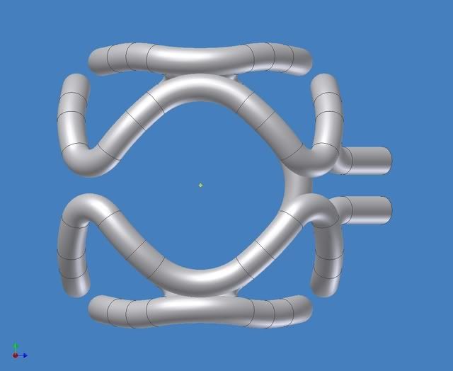
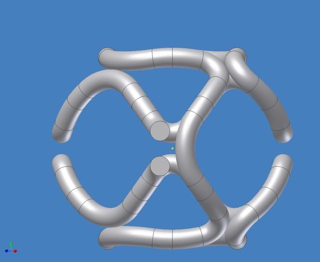
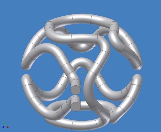
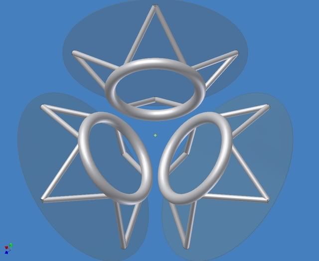
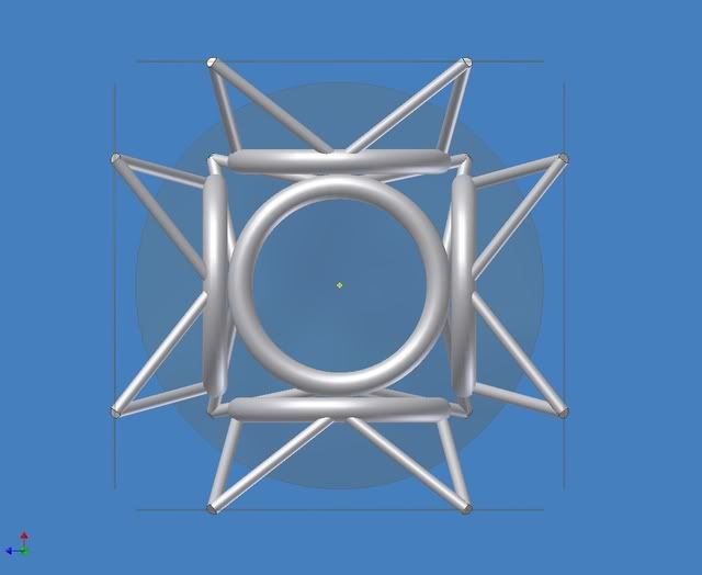
Here is how my previous pictures look with the 20” thick 4 meter centerline diameter coils.
http://i299.photobucket.com/albums/mm31 ... Corner.jpg
http://i299.photobucket.com/albums/mm31 ... atFace.jpg
http://i299.photobucket.com/albums/mm31 ... edline.jpg
http://i299.photobucket.com/albums/mm31 ... Offset.jpg
http://i299.photobucket.com/albums/mm31 ... iewFat.jpg
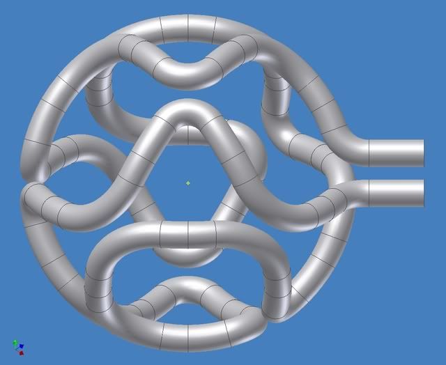
-Tom Boydston-
"If we knew what we were doing, it wouldn’t be called research, would it?" ~Albert Einstein

KitemanSA
Posts: 6179
Joined: Sun Sep 28, 2008 3:05 pm
Location: OlyPen WA

Post by KitemanSA »

tombo wrote: The advantage of the one pass is no “nubbins” no splices, no tees, no joints etc.
The magnetic field shape is the same as MPG which Dr B liked and which actually made a whiffle ball.
The forces on the 25 V’s should be balanced along the surface of the sphere.
Sphere = vacuum chamber shell?
tombo wrote:There will be a net outward force on all segments and yes I expect it to be higher where the curvature is higher.
By "outward" do you mean tending to open up the "v"s? If so, I think I disagree. There may be the attempt by one magnet to open it up, but the magnet next to it is pushing the other way on each of the segments. Net cross beam load, nil. There WILL be a load pointing radially outward from the center of the MaGrid. Those are taken up easily by my design.
tombo wrote:I am concerned about the square cross section SC turns. They might be easy to wind on a standard shape bobbin but:
When the current ramps up they are going to “want to” pull together (like a Z-pinch plasma) into a round shape, also they are going to push away from the center of the coil (off the bobbin id) then they are going to push away from the center of the sphere (up against one side of the bobbin).
It is going to take more math than I know to determine the minimum energy shape (cross section). But, I would bet that it is not square.
But square would really help the layup process! :wink:
tombo wrote:I don’t intend to snake the sc through the 25 bends. I intend to build the nested assembly straight then bend to shape using the interior parts as a built in mandrel. Google “hydraulic tubing benders”. Sources suitable up to 5” pipe come up in the first couple of hits. The technology is scalable.
But the SC wire probably won't take that kind of strain. Anything more than ~0.2% and you start losing capacity fast. Some toughened wires go to 0.4%!
tombo wrote:This idea becomes much harder as you push the diameter from 8” up to what is it now 20”?
I should guess so! :lol:
tombo wrote: Kiteman, My program will not slice like that. It would be easier to build up 4 whole assemblies at different radii and nest them. I think I see what you are driving at though. Do you mean to have the whole thing in 1 casing or do you envision 4 separate casings?
How bout the "union" idea? Anyway, for a first try, can you just make the pipes rectangular cross section, 1" radial for each 4" transverse, and the duplicate it 3 times at the appropriate extended radius? This would result in the square cross setion SC core that folk are bandying about.
tombo wrote:The former seems really difficult to fabricate and there is no where for the electrons to re-circulate.
Hunh? Are we talking about electrons in the superconductor or electrons in the plasma?
tombo wrote:It makes for essentially really big nubbins.
Actually, it makes for quad REAL magnets and NO nubbins (nubbins being defined as those little cross pipes in the middle of the funny cusps that carry little or no current and just get in the way!)
tombo wrote:The latter runs up against a problem that has been pointed out before (insert embarrassed smiley) which is that it leaves field nulls when you look closely. This is why Dr B called for polyhedrons with even vertices.
True. He anticipated it, they're called "funny" cusps and he didn't seem to care. He just made a mistake by putting the nubbins in the middle of them.

Billy Catringer
Posts: 221
Joined: Mon Feb 02, 2009 2:32 pm
Location: Texas

Post by Billy Catringer »

Okay, here it is revised. That is to say that the diameter on the center line of the SC core is now 2 meters. The SC core is 29cm x 29cm square as Chief Simon requested.

http://www.flickr.com/photos/36049122@N ... 1/sizes/o/

The LHe jacket is 58.24cm OD in cross section with a wall thickness of 1.27cm 316SS.

Vacuum Jacket 01: 63.32cm OD with a WT of 1.27cm, 316SS.

LN2 Jacket: 81.10cm OD with a WT of 1.27cm, 316SS.

Vacuum Jacket 02: 86.18cm OD with a WT of 1.27cm, 316SS.

Cool Water Jacket: 109.42cm with a WT of 4.00cm, Inconel 690.

Vacuum Jacket 3: 114.50 cm with a WT of 1.27cm, Inconel 690.

Hot Water Jacket: 133.55cm with a WT of 1.90cm, work hardened copper.

The SC core by itself will weigh something close to 8,500kg. Total weight of one magnet assembly (not including pedestals) with all coolants filling their respective jackets is about 55,000kg.

I'm thinking we still have a ways to go to optimize this beast. I'll post a better chart of everything tomorrow. It is 0300 hrs where I am at and I'm too tired to continue.

Post Reply