Is There an Optimal Size for Magrid Casings?
-
Billy Catringer
- Posts: 221
- Joined: Mon Feb 02, 2009 2:32 pm
- Location: Texas
DrB didn't want them round. I REALLY like the MPG as a starting point.tombo wrote:
I would welcome any suggestions about tooling.
I'm thinking corrugated cardboard (apple box, duct tape) and zip ties with a few dozen turns of transformer wire.
But, I would really like to find a cheap/free round form to wind them on and to hold them properly round during the measurements.
Rather that a single pass MPG, I would propose a multi-pass variation (which could be done reasonably easily on a spherical form) with an additional twist. The MPG had the feed coming in from one corner of the top (north-pole) "square" of the cuboctohedron. It would be quite feasible to lay the above mentioned multi-pass MPG such that the winding are rather flat, and then bring in three overlaying layups, one from each additional corner of the north polar square. This would cause each funny cusp to be surrounded by nearly full strength magnets, protecting all metal surfaces.
As I said, this would actually be a reasonably simple lay-up on the spherical core, everything being snugged around the sphere.
I've laid it out for a non-SC cryo-magnet (uses square copper tubing layed up in parallel, open ended at the inlet for each stratum, and connected quasi bitter magnet like from one tube to the next.
Each lay-up would be separately encased in formed stainless sheet (punch-pressed?). Further, between the layups (all or some) could be inserted a strength band. ... Ah fooey. Ain't English wonderful for describing geometric shapes!
Is there a wiki we can do this at? Some place where we can post files/sketches and cross edit words? Might go a lot easier.
Does Photobucket allow posting things like powerpoint presentations? If not, where might I post one that can be accessed?
Welding and leak testing vacuum vessels is a lot more tricky than pressure piping. Although those specs are a good start.
It is a specialty of its own and I think those welders are even further beyond my wallet than the usual ones.
What kind of cage? I'm not visualizing what you mean. Sketch?
Moly and titanium are quite available but tricky to fabricate.
Carbon fiber is available by the container load.
CNT's? not this year.
My point is that with the right materials cooling might not be required in selected spots.
I'm looking forward to seeing your sketches.
The circular coils on cardboard were just to get some force measurements to verify loads and stability.
Yes, I like the MPG.
I like bitter coils too.
I can't quite see your geometry though.
I used to tell people trying to do this on the phone the hang up and fax me a sketch, then we can talk. Saved hours and hours of frustration that way.
Yes, English or any verbal language just does not have the bandwidth needed.
It is a specialty of its own and I think those welders are even further beyond my wallet than the usual ones.
What kind of cage? I'm not visualizing what you mean. Sketch?
Moly and titanium are quite available but tricky to fabricate.
Carbon fiber is available by the container load.
CNT's? not this year.
My point is that with the right materials cooling might not be required in selected spots.
A lot more than that if I know my Murphy. I did not mention all of the ones I noticed, as I figured you would be seeing the most obvious ones.You missed one or two of the demons
I'm looking forward to seeing your sketches.
The circular coils on cardboard were just to get some force measurements to verify loads and stability.
Yes, I like the MPG.
I like bitter coils too.
I can't quite see your geometry though.
I used to tell people trying to do this on the phone the hang up and fax me a sketch, then we can talk. Saved hours and hours of frustration that way.
Yes, English or any verbal language just does not have the bandwidth needed.
-Tom Boydston-
"If we knew what we were doing, it wouldn’t be called research, would it?" ~Albert Einstein
"If we knew what we were doing, it wouldn’t be called research, would it?" ~Albert Einstein
-
Billy Catringer
- Posts: 221
- Joined: Mon Feb 02, 2009 2:32 pm
- Location: Texas
Been there, done that. The shells around the SC electromagnets are basically pipe.tombo wrote:Welding and leak testing vacuum vessels is a lot more tricky than pressure piping.
tombo wrote:Although those specs are a good start.
Ah, at these temperatures and pressures, B31.1 is The Code and you keep to The Code because powers greater than those of Calypso enforce them.
tombo wrote:It is a specialty of its own and I think those welders are even further beyond my wallet than the usual ones.
That's true. This isn't something that will be built in Bubba Jone's garage, unless Bubba happens to be a very good welder and has a buddy with deep pockets.
tombo wrote:What kind of cage? I'm not visualizing what you mean. Sketch?
Blender file. I haven't done that yet. It will be the structure necessary to hold the Magrid together. It will be tricky. It will have to be set back far enough not to interfere with the quantum fuzzy-wuzzies we want to bash together.
tombo wrote:Moly and titanium are quite available but tricky to fabricate.
Yes, they are, though expense to buy and even more expensive to work with. How well will those materials hold up to neutron activation?
tombo wrote:Carbon fiber is available by the container load.
And the epoxies that hold carbon fibers together? How badly will they outgas in a vacuum? I am asking because I don't know.
tombo wrote:My point is that with the right materials cooling might not be required in selected spots.
True. Can you show me said materials?
tombo wrote: A lot more than that if I know my Murphy. I did not mention all of the ones I noticed, as I figured you would be seeing the most obvious ones.
No one EVER finds all the demons on the first pass. Having more than one pair of eyes to look at the first design is a huge help. And you have been a great help. Keep it up.
tombo wrote:I'm looking forward to seeing your sketches.
So am I. What usually happens to me is that I go without work until I commit to getting my garden going again. This time, work came in after I committed to building this model in Blender. I am hoping to have more time to devote to this project starting Monday of next week.
tombo wrote:The circular coils on cardboard were just to get some force measurements to verify loads and stability.
I am a little more worried about coolant flow rates through toroids, cavitation and vibration in same. These shells are not closed loops of pipe. They will need partitions to make the fluids flow correctly.
BTW, Chief Simon, I think we had better plan on using Inconel 690 for the cool water jackets. There are well established procedures for welding it, but I don't know about castings in Inconel 690 and I DO know that it is hard to machine. The last feature is a not-so-minor sin, but we will have to live with it, I think.
-
Billy Catringer
- Posts: 221
- Joined: Mon Feb 02, 2009 2:32 pm
- Location: Texas
Okay, paying work is gone. I'm back to work on what I see as my truly important work. I don't know if I am a harmless drudge, a hapless drudge, or a harmful drudge. One thing I am certain of is that I am a willing drudge. Why? Because I want to see this thing work. Why? Because I want to undermine the control of our governors. God bless their flabby black hearts.
Yeah!Billy Catringer wrote:Okay, paying work is gone. I'm back to work on what I see as my truly important work. I don't know if I am a harmless drudge, a hapless drudge, or a harmful drudge. One thing I am certain of is that I am a willing drudge. Why? Because I want to see this thing work. Why? Because I want to undermine the control of our governors. God bless their flabby black hearts.
Engineering is the art of making what you want from what you can get at a profit.
Kiteman,
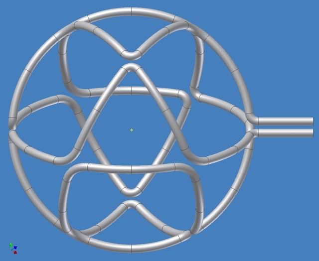
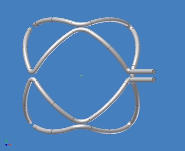
You asked to see the MPG-like truncube with bowed edges (following the surface of the sphere).
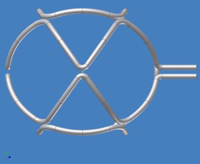
Here is a view looking at a corner:
Here is a view looking at an edge:
You can see from this angle how the turns really do line up with each other.
http://i299.photobucket.com/albums/mm31 ... Assy2A.jpg
You probably wonder why it looks oval. That is because the circles are foreshortened. Another way to think about it is that the theoretical sphere protrudes further through the coils at the square openings (top and bottom of this view) (6 & 12 o'clock) because they are larger than the triangular ones (like at 2, 4, 8 & 10 o'clock) and does not protrude at all at the left and right extremes (3 & 9 o'clock). There is also a bit of optical illusion involved. Use a ruler.
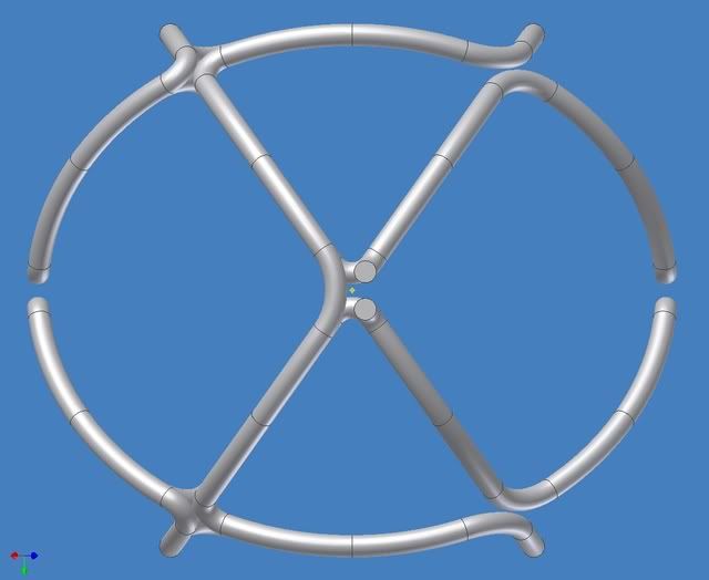
Here is a view looking at a face:
http://i299.photobucket.com/albums/mm31 ... Assy2B.jpg
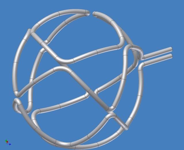
Here is a view looking at an arbitrary angle:
http://i299.photobucket.com/albums/mm31 ... Assy2C.jpg
Here is a view looking at the feedlines:
http://i299.photobucket.com/albums/mm31 ... Assy2D.jpg
I left all but the first of these as links to avoid cluttering the page.
These are shown based on a cube with 4 meter sides and 8" thick conductors (per msimon's numbers above and on another thread).
These parameters are easily adjustable.
You asked to see the MPG-like truncube with bowed edges (following the surface of the sphere).
Here is a view looking at a corner:
Here is a view looking at an edge:
You can see from this angle how the turns really do line up with each other.
http://i299.photobucket.com/albums/mm31 ... Assy2A.jpg
You probably wonder why it looks oval. That is because the circles are foreshortened. Another way to think about it is that the theoretical sphere protrudes further through the coils at the square openings (top and bottom of this view) (6 & 12 o'clock) because they are larger than the triangular ones (like at 2, 4, 8 & 10 o'clock) and does not protrude at all at the left and right extremes (3 & 9 o'clock). There is also a bit of optical illusion involved. Use a ruler.
Here is a view looking at a face:
http://i299.photobucket.com/albums/mm31 ... Assy2B.jpg
Here is a view looking at an arbitrary angle:
http://i299.photobucket.com/albums/mm31 ... Assy2C.jpg
Here is a view looking at the feedlines:
http://i299.photobucket.com/albums/mm31 ... Assy2D.jpg
I left all but the first of these as links to avoid cluttering the page.
These are shown based on a cube with 4 meter sides and 8" thick conductors (per msimon's numbers above and on another thread).
These parameters are easily adjustable.
-Tom Boydston-
"If we knew what we were doing, it wouldn’t be called research, would it?" ~Albert Einstein
"If we knew what we were doing, it wouldn’t be called research, would it?" ~Albert Einstein
-
Billy Catringer
- Posts: 221
- Joined: Mon Feb 02, 2009 2:32 pm
- Location: Texas
Yes, actually AutoDesk Inventor.
I'm not sure what you are asking for.
All the faces look just like the one I showed.
The only difference is the feed line orientation.
I don't have any "rest of the assembly" drawn yet.
In Inventor if I don't show it just right it looks really bad or non-existent.
I see it as hanging from the feed lines inside the vacuum chamber.
We might or might not need tension ties where the coil bends come closest, depending on the field strengths needed.
They are a detail that will require significant thought.
My first tries will be braze molybdenum strips to the casings or tie them together with several turns of carbon fiber and the proper sailor's knots.
If that fails then the ties need to be tubing integrated into the high temp outer water loop. And as you said that starts to get ugly pretty quickly.
-Tom Boydston-
"If we knew what we were doing, it wouldn’t be called research, would it?" ~Albert Einstein
"If we knew what we were doing, it wouldn’t be called research, would it?" ~Albert Einstein
-
Billy Catringer
- Posts: 221
- Joined: Mon Feb 02, 2009 2:32 pm
- Location: Texas
I am trying to get a better look at the tee connections so that I could figure out the the flow of coolants.
Let me be honest with you here, though. This kind of magrid will be damnably difficult to construct at 2m and 10T. I like the idea because it simplifies flow through of coolants, or appears to, and I think it would likely do a better job of steering our quantum fuzzy-wuzzies, but fishing SC tape through that thing, or even laying it up it split halves is going to be one truly tedious chore.
Why don't you ask EKribbs to look at it. He has qualifications I lack.
I'm sceptical of the design until I see a magnetic field simulation. And then there is the question of supporting it against repulsive forces.Billy Catringer wrote:I am trying to get a better look at the tee connections so that I could figure out the the flow of coolants.
Let me be honest with you here, though. This kind of magrid will be damnably difficult to construct at 2m and 10T. I like the idea because it simplifies flow through of coolants, or appears to, and I think it would likely do a better job of steering our quantum fuzzy-wuzzies, but fishing SC tape through that thing, or even laying it up it split halves is going to be one truly tedious chore.
Why don't you ask EKribbs to look at it. He has qualifications I lack.
Engineering is the art of making what you want from what you can get at a profit.
-
Billy Catringer
- Posts: 221
- Joined: Mon Feb 02, 2009 2:32 pm
- Location: Texas
Perfect start!! Point of clarification: what is the diameter of the inscribed sphere? All those arcs should just touch a sphere. What is the diameter of that sphere?tombo wrote:Yes, actually AutoDesk Inventor.
I'm not sure what you are asking for.
All the faces look just like the one I showed.
The only difference is the feed line orientation.
I don't have any "rest of the assembly" drawn yet.
Next step: does AD Inventor have the ability to define a slice plane? If so, please slice the unit with spheres at D+2.5", D+4", and D+5.5" given D= diameter of inscribed sphere. When done, each slice can be rotated 90 degrees about the north pole (the blue axis as shown herein).
When this is done, the unit should look exactly like it does now for all the arcs, but it gets locked into a cohesive whole with no open gaps. True, the corners will not have a full complement of conductors, only 1/2 in each if I am correct. There will be corners on the "coils AND the "virtual coils", and the funny cusps will not be line-like anymore. Each intersection will look like a large X with an elongated hole in the middle.
To simplefy the drawing of it, just add the small corners wherever you have the large ones, and vice-versa.
The idea here is to have four strata of coils, one each fed from a corner of the north pole square shown above. Where you have one pair of inlet/outlet lines, there would be four. Each stratum would be cooled seperately and would use a counterflow pattern to equalize the cooling.
One other thing, a strength backbone can be placed between the middle two strata and it would be in pure membrane stress as a first order approximation, pure hoop if you will. Each stratum would then be attached to that backbone.
Laying up square copper tube in such a pattern would be simple. SC tape would be more difficult but not too bad (I think). Remember that since this is being layed up around a sphere, there is a core to wind on, so layup is made the easier therefore.
It strikes me that a possible alternative to slicing planes is to do a union between your MARVELOUS rendition and a set of spherical shells of the proper diameters and thicknesses. For example, if you generate a sphereical shell with an ID=D and an OD=D+2.5" and do a union between it and the rendition, you SHOULD be left with the shape of the first (inner-most) stratum. Do it again 3 more times and the slices (strata) are yours to play with.I wrote:Next step: does AD Inventor have the ability to define a slice plane? If so, please slice the unit with spheres at D+2.5", D+4", and D+5.5" given D= diameter of inscribed sphere.
If you then do the 90 degree twistings discussed above, we might learn something good.