ekribbs wrote:I am submitting a description of my vision of a design which does not have tension supports as requested by Billy Catringer.
Sorry, Billy, I have no pictures, so I will do my best to describe my idea.
Ed, I greatly appreciate you're taking a hand in this, make no mistake about it.
ekribbs wrote:You want six 2 meter magnets in WB-6 configuration. I assume the requirement of no tension supports means removal of the "nubs" discussed elsewhere.
Absolutely. They are, as I understand it, in the way of particle circulation and I can see no way to cool them reliably. As much as this thing needs supports in tension, I have yet to find a way to install them without causing major trouble.
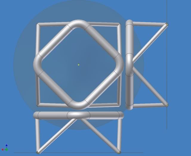
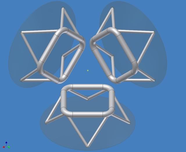
ekribbs wrote:I imagined this intermediate structure to be a truss. Imagine the truss to resemble a short, miniature oil rig. Imagine the magnet torus stuck to the top of the mini oil rig, and the base of the rig welded to the inside of the vacuum chamber. I imagined all the cooling, power and control wiring for each magnet to be fed through the legs of the truss piping to the outside of the vacuum chamber. I also imagined thick, free-floating ceramic insulators on the legs of the truss pipes, which must penetrate the outer negatively charged mesh, and thick insulators between the top of the truss to the magnets.
I started off thinking that we would be required to build these with an absolute minimum of clutter inside the vacuum vessel. I would imagine that keeping it as clean as practicable is still a requirement. However, when I first began to imagine what this thing would look like I expected them to be standing inside the vessel on twin stalks side by side coming out of the edge of each torus, rather like a lollipop with two sticks. Two obvious flaws with this approach became apparent after I thought about it. One is that assembling the structure with the necessary coolant piping would be exceedingly difficult. The other one was that the "lollipop" configuration would be unlikely to properly deal with all the forces imposed by and on the magnets.
ekribbs wrote:Now the length of the truss can be a problem. If the distance from the magnets to the vacuum chamber walls is long, you are going to have a vibration problem. If you have the funds to build a new vacuum chamber, make the truss as short as you can so as not to interfere with electron/Ion recirculation, and make the new vacuum chamber fit to the outside of that.
I think that we will need to build a vacuum chamber around the physics. That means we will be building a new vacuum vessel and a rather large one at that. However, we cannot do much on the design of it until we have a fair idea on two things. First is the magnet assembly the other is what I think of as the "alpha catcher". The two questions that come to my mind are; "How far away from the center of the magnet assembly does the "alpha catcher" have to be and how big is the "alph catcher"?
My best estimates suggest that each magnet with its coolant jackets and its coolants will weigh over 55,000kg. This figure does not include the supports that attach the torii to something solid and it does not include the weights of the shoes transferring the loads from the SC coils to the structure of the torii. While trying to model a likely shoe last night, it dawned on me that the shoes for the LHe jacket, the LN2 jacket and both water jackets will add some significant weight. More on the weights later, perhaps in another post, but for now let's say we are talking about magnets that will have operational weights of about 60,000kg.
ekribbs wrote:Why a vibration problem? There will be lateral forces as well as the axial magnetic forces. Lateral forces deflect the magnets. Deflection changes the magnet spacing. That changes the magnetic field. That changes the lateral force. That re-changes the lateral deflection. On and on.
I have been worried about vibration from the git-go. On top of the magnetic forces wanting to shove everything around, we are also pumping coolants through the whole thing. There are many sources of vibration in the system and all of them could cause major trouble when you stop to think that we would be jiggling 60 Teslas worth of magnetic fields around. Moving fields of that magnitude would likely generate enough current in your fillings to give you an electrically induced heart attack.
Whether or not we use bumpers, or use additional supports would be determined by the physics. We dasn't put anything in the way of our quantum fuzzy-wuzzies because that would defeat the purpose of our machine. I would not have a problem with bumpers if the physicists do not cry foul. That seems to be the simplest solution, even if it proved necessary to mount them on water cooled spring cans.
ekribbs wrote:All of those reinforcements to make the trusses Not Cantilevered, of course, would be unnecessary if the vacuum chamber were designed to fit the magnet truss assembly. For your case, such a vacuum chamber would be spherical. Make the trusses as Short and stiff as possible to allow the trusses to be Cantilevered and also by shortness and stiffness resist vibration. Making the base of the "oil rig" truss much wider than the top will also help to resist lateral forces and vibration.
So it shall be. I will model it per your advice.
ekribbs wrote:At least have a first natural eigenvalue (frequency) of the truss and magnet assembly to be so high that it will not resonate with the magnet forces. A full finite element model of the spherical vacuum chamber with all six trusses and magnets included may be necessary to obtain the real modes of vibration. Short of that, you may make a model of one magnet on its truss and a portion of the vacuum chamber. Then enforce symmetrical boundary conditions at the edges of the portion of the vacuum chamber wall.
Okay, I'm caught. I have been trying to pull a Tom Sawyer and lack the nerve to con you into white washing my fence.
I did just a wee bit of this back in the late seventies when you paid for time on a mainframe and talked to the mainframe with a printer, a 300 baud modem with a phone coupler--no monitor. I entered the data for my engineer boss and gave him the print outs. I also walked down the steam system we were analyzing and marked up as built drawings. I translated the drawings into the descriptive code the software needed to do the analysis. So, while you might say that I know what needs to go in, the outputs will tell me nothing and I have not worked with a modern FEA package. Yes, I need help whitewashing the fence, or will need it once I have a complete model.
ekribbs wrote:Pre-loading is important! You need to do a FEA vibration problem with all the expected forces included, magnetic and structural pre-loading, if applied. The pre-load is important because it influences the natural frequencies. That is how you tune a violin, remember? You tension the strings with the knobs on the end.
And the pre-loading helps to kill the vibrations before they can get into step. Gotcha.
ekribbs wrote:Good luck.
Thanks, Ed. Now I know which directions to look in. I still have a long, long worry list, but worrying is one of the things I am typically paid to do.
Do stop by and air your own ideas whenever the mood takes you. I know you have something completely different in mind and, if you would like, I'll even take a shot at putting a digital model together for you.
