Page 19 of 23
Posted: Mon Mar 30, 2009 2:12 pm
by KitemanSA
hanelyp wrote:KitemanSA, could you adjust your calculations to get field strength and direction exactly on the lines dividing the square "not a coil" in half? And especially dead center of the face? As I expected, the field close to the center is looking pretty weak in your plot. Calculation of the same plane for WB-6/7 style kissing coils would also be of interest.
Could you post your spreadsheet someplace for us to experiment with?
I am not sure what you are asking for. Dead center of the roughly rectangular reagion of the not-a-coil (lets call it the hole from now on please?) will always be a radial field in the X-cusp and a null field in the Funny cusp. The distinction is the X-cusp has no metal in the way, unlike the Funny cusp and the current WB6&7.
The plot I showed does not include the radial portion of the field. I am still figuring which way is best to present that. Remember, I have to seperately plot each point on a visio sketch to present anything. It is tedious!
The X-Cusp is an odd sort of combination between the funny and the line cusp. If you follow the pure polyhedral magnet lines in, there is a null at the center of all the coils, so there is a null at the center of the vertex also. With the X-cusp, there virtual coils that kind of split the difference between the two real legs and connect to the vertical symmetry line about half way out each span from the horizontal symmetry line. Inside the hole, the field at the mid-plane of the coils switches from outward at the horizontal symmetry line to inward about half way up, and back to outward outside the hole. But that whole hole mess is covered pretty well by the tangential field inside the MaGrid, except at the very center, which is a radial field like a line cusp, but
the X-cusp has no metal in the way.
I am willing to have my spreadsheet posted. How?
Posted: Sat Apr 04, 2009 8:20 am
by tombo
What I see you saying is:
Yes, there is a null field X in the hole in the “plane” of the coils.
But, looking off that plane (either inside or outside) by say the spacing of the coils the field is not null but mostly tangential (to the sphere).
And, that the electrons must travel through that non-null zone to get to the null field zone.
And, that the off plane field is not null because the 4 different zones of (now) tangential field merge smoothly except near the very center of the X where the streams (of field lines) buck each other and dive radially through the center of the hole.
I think I can tentatively buy that. But, I sure would like a real physicist to weigh in on it.
Another feature I see is that if the hole is say 4x taller than it is wide the 4 regions with the X null resolve into 3 regions with 2 crescent nulls connected by a non-null line-cusp.
I think if the crescent shaped nulls are small enough and bent sharply enough then it will be very difficult for a gyrating electron to escape through it, because the electron’s gyro orbit would need to be a potato ship shape to fit through it. What are the odds against that happening? I’d say very long odds. (I’m talking electron population statistics here, in addition to figuratively.)
Another approach would be to move say the top and bottom legs of a squarer hole outward (radially) by say the width of the hole. (Less might do.) This makes the entrance to the null field X from the inside a vertical (on the page of your picture) line cusp and the exit from it on the outside a horizontal line cusp. This configuration blocks both “polarizations” of gyro orbits. I think it also greatly reduces the size of the null zone.
My mental analogy (pneumonic?) is that the fields are now not running directly into each other but grazing and merging with one another.
These 2 variations could be combined for additive effect.
This could possibly be done without bending anything out of the surface of the sphere by simply adjusting the relative radii of the ~60 degree bend and the ~90 degree bend.
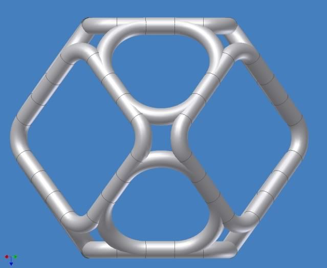
You can almost see it in this picture from March 12, even though I was trying to minimize the effect.
Posted: Sun Apr 05, 2009 12:50 am
by KitemanSA
Here are some results of my MaGrid analysis. Sorry, it is in Excel so the graphics are shaped by the available plot routines (business oriented mostly). What I have plotted is the magnitude of the tangential field at the points on a plane 10 units inward of the MaGrid.
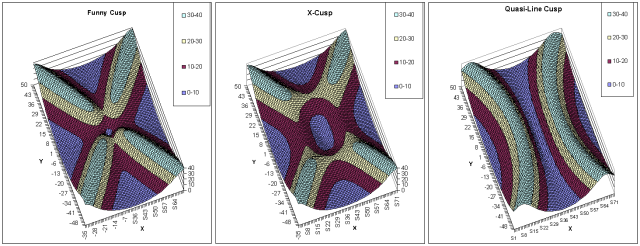
The left is the simple 4 fields at a vertex "Funny Cusp". Note there is a null tangential field right in the middle where the coils cross. There is metal there to quench the electrons. On the right is a WB6 like arrangement. It includes the interconnect field too. There is a linear field void (quasi-linear cusp" between the two coils. There is metal here too, though not as much as the Funny Cusp. In the middle is my proposed arrangement. Yes, there is a field void here too "X-Cusp" but under that void there is NO metal. ALL the metal is behind significant tangential field which will protect is from the electrons.
Folk, given this total lack of exposed metal, AND the fact that it results in a REALLY strong and solid structural configuration, this seems the best way to go so far.
Dana
PS: I really love your graphics. What you show is an un-bowed varient of my proposal with modified dimensions on the X cusp. I think I prefer bowed since I
THINK is will make for a more spherical overall field, but that is TBD. Also, the exact dimensions of the X-cusp is certainly up for discussion and detailed design tweeks. But the idea is sound, I believe.
PPS: Your description of halfmoons and the like in the radial plot at the midplane is accurate. I will plot it out soon and you will see the nulls as you describe.
Posted: Sun Apr 05, 2009 6:29 am
by tombo
I only showed the unbowed version because it was done and available to show (poorly) the point I was trying to make.
Your plots are a lot better than I have be able to get out of excel. Good job.
As the more experienced plasma people explained in another cusp discussion some time ago:
The "quasi-linear cusp" between the WB6 coils is NOT a void or null field but a region of radial field where 2 sets of field lines merge.
It is a strong field compared to the centers of the coils.
In spite of the field strength, electrons with a particular gyro-orbit orientation and velocity can get through, because it is shaped like a portion of the equator of the 2-coil cusp device.
But, yes, it is definitely not a place to put unshielded metal.
Looking at your center chart, it looks like neither of the cross connects are very well shielded.
The y direction ones get down to ~18 units at the saddle and the x direction ones get down to ~22 units.
Compared to the fully shielded (full current) combined coils running ~40 units that is 45% and 55%
I suppose that is reasonable considering that they each have half the current of the main coils.
Posted: Sun Apr 05, 2009 12:00 pm
by KitemanSA
tombo wrote: I only showed the unbowed version because it was done and available to show (poorly) the point I was trying to make.
Your plots are a lot better than I have be able to get out of excel. Good job.
Thank you.
tombo wrote:As the more experienced plasma people explained in another cusp discussion some time ago:
The "quasi-linear cusp" between the WB6 coils is NOT a void or null field but a region of radial field where 2 sets of field lines merge.
It is a strong field compared to the centers of the coils.
I agree completely, but what reflects the electrons back into the reactor volume is the tangential part of the field. If by some magical means the field were all radial everywhere there would be no containment. The strong radial does not itself reflect anything, AFAIK.
tombo wrote:In spite of the field strength, electrons with a particular gyro-orbit orientation and velocity can get through, because it is shaped like a portion of the equator of the 2-coil cusp device.
But, yes, it is definitely not a place to put unshielded metal.
So true.
tombo wrote:Looking at your center chart, it looks like neither of the cross connects are very well shielded.
The y direction ones get down to ~18 units at the saddle and the x direction ones get down to ~22 units.
Compared to the fully shielded (full current) combined coils running ~40 units that is 45% and 55%
I suppose that is reasonable considering that they each have half the current of the main coils.
Not as well shielded merely means that the coil can MAY have to be reduced in diameter to allow more of the field to work. I have acknowledged that since day one. But that is a detail for final design.
Please note that the field over most of the area "within" the magnets (outside the X-Cusp boundaries) are at a much lower tangential field strength than the cross connects and they become part of the wiffleball. If that field is strong enough to contain the electrons, I have trouble seeing how stronger tangential fields will have any trouble at all. If the electrons are contained, how do they reach the metal?
Art, am I just plain wrong here?
Posted: Sun Apr 05, 2009 4:02 pm
by KitemanSA
Here is that radial field comparison I mentioned. This is at the mid-plane and in order to show the detail a bit I shrunk the minor radius to 5 units vice the 10 I had been using before. In point of fact, in my analysis, the minor radius makes no difference on any plane that is at or further than that radius, so the first set of plots were effectively radius independent.
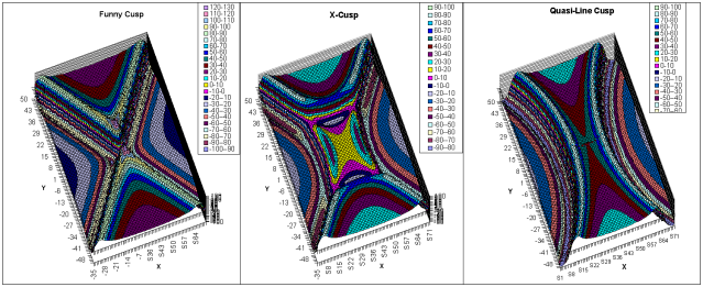
Again, the left is the ideal "4 fields at a vertex" setup and the right is the WB6 like configuration. You can make out the cross connect at this plane and radius.
In the X-Cusp, you can just make out (I'll need to provide the plots individually next time so they will be bigger) that the positive field (north out) in the hole (pink and yellow) become negative (dark blue and grey) in that half mood crescent type shape tombo mentioned. Well considered Tom.
Posted: Sun Apr 05, 2009 4:30 pm
by Betruger
Kiteman did you post the Excel sheet that these last graphs are from somewhere?
Posted: Sun Apr 05, 2009 8:00 pm
by KitemanSA
Betruger wrote:Kiteman did you post the Excel sheet that these last graphs are from somewhere?
I am willing to but have no idea how to. Suggestions? Does photobucket accept "not photos"?
Posted: Sun Apr 05, 2009 8:11 pm
by Betruger
I don't have a webhost of my own anymore, but I do have an old, small account with homestead. How big is the file?
Posted: Mon Apr 06, 2009 12:37 am
by KitemanSA
About 2.5 megs.
Posted: Mon Apr 06, 2009 6:40 am
by choff
Another dumb question, is it absolutely essential that the coils be donut shaped. Could cylindrical coils be used as long as the ends are rounded, longer coils would allow for more coolant piping, less overall surface area facing the plasma, the chamber would have to be bigger. So long as the electrons can circulate around the coil casing without hitting them it should work just as well.
Posted: Mon Apr 06, 2009 2:54 pm
by KitemanSA
choff wrote:Another dumb question, ... should work just as well.
The cross section of the minor dimension is not required to be round. Indeed, this has been discussed in many threads already. And your concluding line is the same basic conclusion that others have made and agreed to.
Posted: Mon Apr 06, 2009 3:56 pm
by Betruger
Kiteman I sent you a PM with my email address, for you to send me the file and me to host it for you.
Posted: Tue Apr 07, 2009 4:23 pm
by KitemanSA
File emailed and description sent by PM.
Posted: Fri Apr 24, 2009 4:43 am
by KitemanSA
I wrote:File emailed and description sent by PM.
Betruger, status of posting?