Page 1 of 3
Alpha collector geometry idea...
Posted: Thu Jul 03, 2008 12:01 am
by 93143
I think I may have a candidate geometry for direct conversion.
Outside the trap grid, put long repeller spikes in the centres of all the 'windows'; that is, the areas of irradiation between the magrid shadows.
Put thin radially oriented walls in the magrid shadows. Separate these walls into two metallic zones at two different radii, at potentials corresponding to the high-band and low-band alphas, with enough insulation distance between them to prevent arcing around the insulation.
If these 'collector wells' are deep enough (physically, I mean - I'm not talking about electrostatic potential wells for once), we shouldn't need much lateral acceleration potential (=energy loss) to get all the alphas to curve over away from the central spike and hit the collector plates (which are no longer at the chamber wall but perpendicular to it). This will make the reactor vessel quite large, but it might be worth it for the efficiency.
Note that high-band alphas don't actually need to curve over all the way to the side of the collector well if the outer wall remains metallic and stays at the high-band collection potential.
In order to minimize difficulties in running power leads through this thin-walled configuration, perhaps it would be better to have the collector plates start out thick at the wall and taper towards their inner radius.
After all my ranting about Gauss' Law, I'll be real embarrassed if this turns out to be unfeasible for some simple physical reason like that...
Posted: Sat Jul 05, 2008 1:16 am
by rcain
you mean a bit like a sort of graduated anechoic chamber - an absorption filter if you will?
i was thinking of similar sorts of arrangements a while back to mitigate collisions with the grid coils - studying some of the models at
http://www.falstad.com/mathphysics.html and seeing how charged particles behave around spikes, edges, corners, etc; wondering if they could be made useful rather than problematic.
are we on a similar wavelength?
Posted: Sat Jul 05, 2008 4:32 am
by 93143
Possibly. You can't collect alphas with a wire grid because they miss. So the basic idea is to get them to curve over and intersect (at the lowest possible energy) with a radially-directed plate. The repeller is mainly to speed up the process so the resulting vacuum chamber is still smaller than ITER...
Though now I think of it, the intersection energy might have to be pretty low to avoid massive sputtering... this could limit how small you can make the system...
Also, I think any sort of spike (anything actually sharp) is going to be anathema because of arcing... My "repeller spike" would probably be almost as big around as the magrid coils and have a hemispherical tip. I think short pulses in the magnetic field synchronized with the collapse phase of a POPS oscillation is a better bet for minimizing magrid alpha intercepts.
Posted: Sat Jul 05, 2008 8:04 pm
by Jccarlton
You now this is the sort of thing that could be done independently. All we need as a vacuum chamber, a high voltage setup and some design ideas. We come up with a low energy linac and pump in Helium to bombard the grid.
Posted: Sun Jul 06, 2008 3:16 pm
by MSimon
Jccarlton wrote:You now this is the sort of thing that could be done independently. All we need as a vacuum chamber, a high voltage setup and some design ideas. We come up with a low energy linac and pump in Helium to bombard the grid.
True. A 1 to 2 MeV alpha accelerator with associated eqpt would be a good test bed. OTOH most of the work should be done with simulations with results experimentally verified.
Right now without a map of energy/space distributions we are flying blind. Plus what is the real shadow (including magnetic effects) of the grids?
We are going to have to build a lot of reactors at all scales to work out the engineering.
Posted: Fri Jul 11, 2008 5:27 am
by tombo
93143 something like this?
http://i299.photobucket.com/albums/mm31 ... orAssy.jpg
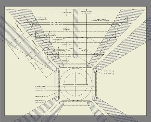
This is really quick and dirty just to have something to look at.
The first thing that jumps out at me is how rapidly the side electrodes diverge.
They would diverge more slowly in a dodecahedron.
The nasa paper from 1964 looks like a pretty good starting point.
http://ntrs.nasa.gov/search.jsp?R=21685 ... 4294967207
They were talking 10's of meters for this kind of deflection.
It would be good to see what follow up they have done in the succeeding 44 years.
If you would like me to tweak this sketch just ask.
Posted: Fri Jul 11, 2008 6:03 am
by 93143
tombo wrote:93143 something like this?
Yeah, pretty much. I haven't really thought it through far enough to request changes at this point (kinda busy with research this week), but that's the general idea. Nice work.
One thing - if you're trying to catch a continuous distribution of energies with a discrete set of spaced grids, won't a lot of the alphas miss (or hit the insulation between them, if it's one solid structure)? I suspect we may need to just use one collector for the low-band alphas and another (including the wall) for the high-band alphas. I've been given to understand that the low-band spread isn't as bad as I feared, so we may not lose much energy this way...
I'll think about this tomorrow when it's less critical to get to sleep right away...
The first thing that jumps out at me is how rapidly the side electrodes diverge.
There may be ways around this, like broadening the repeller out towards the wall, or something... I should think about it more.
The nasa paper from 1964 looks like a pretty good starting point.
Sadly, I didn't read it soon enough or something. All it gives me now is "Study of an attitude control system for the astronaut maneuvering unit"...
They were talking 10's of meters for this kind of deflection.
Like I said, it might make the system bigger... It might not be worth it for space-based reactors if we can't prevent the alphas from hitting the coils (it might be as low as 10% extra efficiency versus a single collector, which leads to maybe 2/3 as much thermal waste balanced against a much smaller and lighter reactor).
Posted: Fri Jul 11, 2008 6:21 am
by tombo
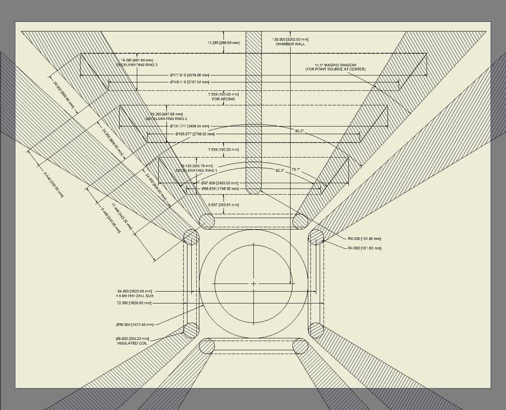
Ok I will float a configuration:
We have alphas at 2.46 MeV & 2.46 MeV & 3.76 MeV
They would be stopped by 1.23MV & 1.88 MV plates respectively.
So if we have the following spheres (starting in the center and moving out) we would get better conversion efficiency.
0V=well
+30kV =Magrid
0V (say) =trap grid
1.22 MV decelerating grid for 2.46 MeV population alphas (tweak for population energy distribution)
(They are now traveling at only 0.02 MeV)
1.50 MV lateral (radial) deflection grids push 0.02 MeV alphas laterally into lateral (radial) collector plates at 1.23(+/-) MV
(But the 3.76 MeV alphas are still screaming along at 760keV so they are deflected only a little)
1.87 MV collector plate for 3.76 MeV population alphas (tweak for population energy spread)
So they only hit it at 0.02 MeV losing little to heating. But are forced to actually hit it and not fall back down into the well disrupting the energy distribution there and taking their energy away from us meddling humans.
These voltages would need to be de-rated due to the energy distribution of the 2(3?) populations of alphas.
Posted: Fri Jul 11, 2008 6:30 am
by dch24
tombo, that design sounds good to me. One question 93143 had was what the shape of the grids/plates for lateral deflection should be -- specifically, he did the thought experiment of lateral deflection using wedge-shaped plates, and noted that the high voltages would not allow a sharp edge on the inside of the profile.
Question for 93143: Assuming that an ellipsoid or anything beveled to a large enough radius, in the MaGrid shadow, does lateral deflection -- then would this have other problems I missed from the previous discussion of lateral deflection?
Question for tombo: How much deflection will the alphas see into the MaGrid shadow from alpha-alpha electrostatic forces, collisions, or other possible effects? I assume as their radial velocity drops the deviation into the shadow will be greater.
Posted: Sat Jul 12, 2008 9:16 pm
by tombo
Actually I would prefer to bend the alpha paths the other way, making the shadowed volume larger and larger as we go away from the center.
The solution would take a 3D path integral of the alpha path grazing the Magrid.
The path would be determined by the maximum potential that could be placed on a deflector while keeping it within the shadow and would in turn determine the diameter and radial spacing of the next segment of deflector.
I’m imagining a series of positively charged rings or tubes with their thickness and spacing limited by the arc breakdown limits.
It might be a losing proposition because the deflection would need to grow more rapidly than the shadows diverge.
Also the alpha source is not going to be a point source but an extended source that in the worst case [for this optimization (but probably better for the Lawson criterion)] would come quite close to the Magrid leaving a very small shadow to start from.
Then the whole thing would need to be done again for the cube corners.
That math I'm sorry to say is beyond me. (Not without many weeks or months of review work just to get started.)
Although, I might be able to solve it piecewise kind of like a coarse integral.
And of course all this is preliminary to detailing out the energy separation floated above.
Oh, there is a problem with the spike. It can’t be negative can it? That will reduce the lateral field available.
Maybe a positive spike is right, but I was hoping to make the shadows into a growing wedge in which to locate the utilities. (You know: power, water, data etc.)
Yes, dch24 you are right Alpha – Alpha repulsion would expand the beam. With any luck that would be balanced by a Z-pinch effect. I would not expect significant lateral effects from collisions at those radial speeds. And, yes, I know it can’t have sharp edges. This picture was just a rough starting point for discussion.
Also, as Msimon pointed out the effects of the magnetic field would also need to be looked into.
As you can see I don’t have an answer here yet.
I’m still churning.
My next step here is to look up minimum radius for given high voltage objects at these pressures and verify the minimum spacing I’m using (25kv/cm from another thread) and I’m sure these are tied together.
But first I’m going to work on viewing Dr Mike’s model of my octahedron.
Uh-oh, I’ve been running off at the keyboard again. I hope I’m shedding more light than heat.
Posted: Sat Jul 12, 2008 10:29 pm
by Aero
You can find the NASA paper on a link from here
http://aeroaero.bravehost.com/
I don't know how my first post got corrupted. I probably didn't do it right.
Posted: Sat Jul 12, 2008 11:19 pm
by Aero
I really do have several questions, the answers to which I believe will cast some light on our problem of shadows and repellers. I want to use a term that is not well defined, at least to me. The term is "fusion core" and by that I mean that particular lumpy spherical area within the polywell where conditions necessary for fusion exist and within which fusion may be expected to occur.
- What is the expected radius of the fusion core of a BFR?
What is the expected radius of the space internal to the Magrid that contains the fusion core?
What is the internal and external radii of the magnets from which the Magrid is constructed?
In order to get these basic numbers it looks to me like we need to pick a design. Fusion may occur at any point within the fusion core and Alpha particles may exit the fusion core in any direction; up, down or sideways and all the other directions, too. Depending on how physically close the radius of the fusion core is to the internal radius of the Magrid, it may or may not cast shadows in which to install equipment. If the fusion core is "small" then our problem is different than if the fusion core is "large" for a given BFR and power rating.
Posted: Sun Jul 13, 2008 12:29 am
by 93143
The low-band alphas won't be a problem. The near edge of the collector will pick them up in the design energy range, so it doesn't matter if they get deflected into the shadow.
The high-band alphas could cause a loss of efficiency if they start hitting the low-band collector in large numbers...
@dch24: I think I misunderstood something. I think the collector plates would actually repel alphas if it weren't for the repeller spike in the centre of the irradiated area. They are, after all, high-voltage incursions into the chamber...
@tombo: You can't make the alphas curve away from the collectors and still have the collectors collect them. If the field is pointed away from the radially-oriented plates, the alphas will never touch them, and you need a different collector mechanism.
@Aero: I would think the fusion core would be fairly small - otherwise we have a problem with fusion-energy ions being at the edge of the wiffleball, which is bad for confinement. But I don't really know. The magnets will hopefully be fairly narrow, so as to achieve better than 80% transparency - a net-power p-11B magrid would be about 3 m across, or so we think.
I wonder - if there aren't shadows, will this work at all? If there's a space in between the two collectors, high-band alphas will enter it, and they... SHOULD have enough radial kinetic energy (yes, that's a valid concept) to make it to the near edge of the high-band collector. If they miss the near edge, the radial field should be zero next to the radially-directed collector plate, so they shouldn't get hauled back into the core, and the next repeller over should push the alphas back into the collector. Even if an alpha did fall back, it would likely be collected on the next pass. (This probably means that gaps are better than solid insulation for our purposes.)
This does not apply in the same way to the problem of low-band alphas passing between two plates in a multigrid low-band arrangement, because in that case the alphas can show up from pretty much anywhere in the irradiated solid angle, meaning they can have substantial lateral velocity and may not be able to make it back to the next collector down. I still think having just two collector potentials is probably optimal.
So yes, it should work. Not as well as I was hoping, and I still haven't done the math to determine whether there's an angle-based or even energy-ratio-based limit on its performance that can't be countered with a larger reactor (now that I think about it, there might be), but I still think it should work better than just crashing everything into a low-band collector.
I haven't had time to do more than skim the NASA stuff. Is there anything in there on dealing efficiently with multiple energies?
Posted: Sun Jul 13, 2008 5:05 am
by tombo
I'm thinking of separate deflectors and collectors with some slim hope of combining them partially.
I don't have a good geometry in mind yet either.
My sketch above was about 1.6M dia and 8" thick coils. Both numbers from other threads. Was that 1.6M radius? Then it is bigger than I thought.
And yes the fall back design is just crashing the high band alphas into the low band collector plate. (and beefing up the plate cooling)
Placing the deflectors and collectors in the shadow is not necessary but it adds efficiency and reduces cooling loads.
The '64 nasa paper emitter has only 5MeV apha's.
Their thinking is much more sophisticated than what we are talking here but their experiments were fairly simple in geometry.
I only skimmed it, but it is good.
Posted: Mon Jul 14, 2008 2:23 am
by Aero
93143 wrote:@Aero: I would think the fusion core would be fairly small - otherwise we have a problem with fusion-energy ions being at the edge of the wiffleball, which is bad for confinement. But I don't really know. The magnets will hopefully be fairly narrow, so as to achieve better than 80% transparency - a net-power p-11B magrid would be about 3 m across, or so we think.
Using the quoted information, I calculated the width (herein, width is used interchangeably with minor torus diameter) of the magnets making up the Magrid for the truncube and dodec configurations. I made the assumption that the diameter (D- major torus diameter) of each magnet of the truncube was equal to the diameter of the Magrid. I further assumed that the diameter of each magnet of the dodec was equal to the radius of the Magrid. These assumptions came as a result of looking at the pictures of the respective Polywell configurations, and have no real foundation other than “It kind of looks that way.”
The approach taken was to first calculate the surface area of the Polywell, calculate the area to be blocked (20%) in square meters, divide that area by 6 (truncube)or 12 (dodec) to derive the area to be blocked by a single magnet. Next, calculate the circumference of the magnet, that is Pi*D, then divide the area to be blocked by this circumference to obtain the blocking width (minor torus diameter) of each magnet.
Thus derived, width of magnets which will block 20% of the surface of the Polywell is 10 cm. It is the same for both Polywell configurations under the stated assumptions. Furthermore:
5 cm width blocks 10%
10 cm width blocks 20%
15 cm width blocks 30%
The minor torus diameter of the magnetic coils being the same in the two different Polywell configurations results from the assumption that the dodec coil major torus diameter was half the truncube coil major torus diameter. That results in the circumference being half also, but there are twice the number of coils so that the sum of all circumferences, in meters, are equal for the two polywell configurations. Therefore, to block an equal percentage of the Polywell’s surface, the minor torus diameters must be equal.
Note: The fact of equal width of the coil for higher order (Dodec) Polywells has implications in cooling the magnets. Smaller diameter magnets may generate less heat per magnet (Is that true?) but have the same cross sectional area available for coolant flow as does the larger magnets of the lower order (Truncube) Polywell. Food for thought.
Note2: Regarding the question of shadows: The fact of small width of the coil for high transparency of the Magrid requires that the fusion core also be small in order that the Magrid cast a shadow. If the diameter of the fusion core is greater than the width of the magnets, the magrid will not cast a shadow. So my next question is, "Will anyone hazard a guess that the fusion core diameter is on the order of millimeters?" "Or centimeters?"
In any case, a curved shadow 10 cm thick (about 4 inches) seems difficult to utilize.