That is what I expected from the close up view. Thanks for the verification.
BTW it looks like a monopole (sort of) at large distances. Interesting.
Which means that if you could get an assembly of particles with the spins all facing "in" we would see a monopole. I wonder if any theoretical guys are looking at this?
2D WB-7 B-filed simulation
-
Art Carlson
- Posts: 794
- Joined: Tue Jun 24, 2008 7:56 am
- Location: Munich, Germany
Yep. Broken.kbaugh wrote:The field lines are radial in all directions. Must be a broken simulation, right?
You have a sign error:kbaugh wrote: radial: 2cos(theta) + 2cos(theta-pi/2) + 2cos(theta-pi) + 2cos(theta-3pi/2)
theta: sin(theta) + sin(theta-pi/2) + sin(theta-pi) + sin(theta-3pi/2)
Simplifying,
radial: 2cos(theta) + 2sin(theta) + 2cos(theta) - 2sin(theta) = 4cos(theta)
theta: sin(theta) - cos(theta) - sin(theta) + cos(theta) = 0
cos(theta-pi) = -cos(theta), not +cos(theta)
Sorry - my bad for trying to do trig at 0700. Yes, both components fall off in the far-field approximation. However the sum of the non-radial components of the six fields cancel.
If the simulation is broken I don't quite see it, but would be glad to share the code to whomever wants to help me scrub it.
If the simulation is broken I don't quite see it, but would be glad to share the code to whomever wants to help me scrub it.
Correction: the non-radial components of the four grids that are in-plane cancel. The two out-of-plane fields are still present, and are purely radial everywhere.kbaugh wrote:Sorry - my bad for trying to do trig at 0700. Yes, both components fall off in the far-field approximation. However the sum of the non-radial components of the six fields cancel.
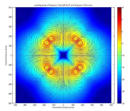
First, my apologies for posting a busted simulation. Let's see if this looks better:
the big picture
The problem with the original version of the model was that I had the current flowing the wrong way in the out-of-plane loops. The in-plane loops established a B-field flowing out of the system, and the two out-of-plane loops had B-fields flowing into the system. The "monopole" behavior was the total field flowing back on itself outside of the analysis plane.
Again, my sincere apologies for the confusion.
No problem. You put your work out there and it got reviewed. That is the way it is supposed to work. We all learn something.First, my apologies for posting a busted simulation.
Second: could you shrink your image to around 90% of what it is now? Maybe with a link to the larger image? What is up now screws up page formatting.
Any way: good on you for doing the work and providing confirmation of previous work.
Excellent.
BTW I have screwed up badly in the past. None of us is immune. But I still love doing my work in the open.
Engineering is the art of making what you want from what you can get at a profit.
To my 'simulation eye', I am not quite sure the original plot is an 'excluded' possibility.
I will suggest that it is common for folks not of a simulating bent to fully appreciate all that can go on in 3 dimensions. There are a few areas of simulation work I have come across this in. People well-versed in their subject become 'blind' to anything beyond 2 dimensions!
Anyhows, let us visualise a scenario in which the magrids 'infront and behind' the screen have their generated field pattern flowing into the centre and in one its fields then flow out through the top and bottom magrids, and the others flow out through the left and right grids. In cross-section, we might now see kbaugh's original plot - viz. it might be plausible under certain conditions, but for the wrong reason.
Why would such a configuration of fields arise? easy - instabilities. If we get a fore-aft motional oscillation (wrt the first pic) of the electrons, then the 'incoming' fields will be caused to follow such patterns as the fields from one grid, and then the other, are 'mirrored'. So the first plot *is* possible, if only as a snapshot of a dynamic oscillation, and thermodynamics will tell you that if it is possible and that it is a step towards minimising system energy (which it would be, you'd immediately loosed your electron population) then it'll happen.
Inventing a machine which involves balancing a ping-pong ball on the head of a pin is fine, in the theory, but the practice of unstable systems is the fatal flaw in many inventions.
I am sure there are some potentially easy fixes to lateral plasma oscillations in this thing, but if any of it works remotely, then I predict such damping will be required.
Thanks to all for the words of encouragment. I was sitting in a meeting at work when I suddenly went "D'oh! The out-of-plane field lines are going the wrong way!".
The model as it sits is in MATLAB, which has a nice streamline generation function. My next step is to (carefully) extend this to a 2D analysis plane arbitrarily oriented in 3D space, with the intent of doing an mpeg of the streamlines and field strength as the analysis plane rotates through the grid system.
The other nice feature of the streamline function is that there is a simple way to evaluate a 3D field along the individual streamlines. Would there be any interest and/or utility in evaluating some performance metric of the system along sets of streamlines ? For example, the "mirror ratio" of highest to lowest magnetic field strength? How about the voltage distribution along specific field lines?
Chris says:
Also see Nebel and Park re: POPS.
It is my contention that such oscillations are a feature not a flaw. Dr. B. seemed to think so as well. Thus open cusps.I am sure there are some potentially easy fixes to lateral plasma oscillations in this thing, but if any of it works remotely, then I predict such damping will be required.
Also see Nebel and Park re: POPS.
Engineering is the art of making what you want from what you can get at a profit.
Radial oscillations would be fine.MSimon wrote: It is my contention that such oscillations are a feature not a flaw. Dr. B. seemed to think so as well. Thus open cusps.
Cirmumferential oscillations would be a big problem.
Lateral (linear) oscillations across the device would cause complete confinement failure.