Hi All,
I have invented a spherical electromagnet that I think might be useful for containing plasma and perhaps for maintaining a fusion reaction.
A photo of it can be found at the following link along with a full illustrations and explanation of how it was built and how I imagine it can be used.
The invention is in the public domain.
http://www.justodians.org/SphericalMagn ... agPic1.htm
Would someone please look it over and tell me if it has a use?
I am also curious to know if anyone else has invented this before me.
Thanks, John
Spherical Electromagnet for Plasma Containment
-
johnshearing
- Posts: 7
- Joined: Fri Oct 17, 2008 1:32 am
- Location: New York
- Contact:
-
Art Carlson
- Posts: 794
- Joined: Tue Jun 24, 2008 7:56 am
- Location: Munich, Germany
-
johnshearing
- Posts: 7
- Joined: Fri Oct 17, 2008 1:32 am
- Location: New York
- Contact:
Hi Solo,
>I guess this would suffer the same issue as my proposal to join the edges of tombo's single-turn coils: the corners will have a field null.<
This device is actually 6 different interlocking coils of wire which are meant to be turned on and off in sequence. The idea is not to contain plasma but rather to juggle it. The following portion of the abstract should make this clear.
This invention proposes that the location of the poles is constantly changing. This is accomplished by varying the current running through the six interlocking coils of wire. So as the hot plasma moves near the poles to escape, that exit is closed before the plasma has a chance to reach it. The plasma now moves towards a new pole and so on around and around inside the bottle. This motion creates a secondary magnetic field within the plasma itself as it spins inside the bottle. And because the axis of spin is constantly changing, a magnetic vortex is formed pushing and pulling the plasma to the center of the bottle.
An interesting experiment would be to hook up a signal generator to 6 channels of digital delay and then into 6 channels of amplification. Then send the amplified signals through each of the six coils of the spherical magnet. The spherical magnet will have a balloon in the center filled with water and iron particles in suspension. By fooling with the signal and the delay, I expect to be able to make the iron particles move about inside the sphere like a school of fish. Since plasma also responds to magnetism, the implication is that plasma may be in controlled the same way.
The full patent application can be read here:
http://www.justodians.org/SphericalMagnet/PatentApp.htm
Hi JMC,
>This looks like the dodecahedral polywell which Bussard referred to.<
I thought the same but then I found, in the design forum, a topic titled "Dodecahedron". This topic discusses the dodecahedral polywell. A picture can be seen in the forum topic which shows something quite different from my invention. Yes the picture is an octahedron and not a dodecahedron. But that is not the difference I am referring to. The difference is the way the magnets are placed in relation to each other.
Please look at the picture of the octahedral polywell shown in the design forum under the topic "Dodecahedron"
http://img525.imageshack.us/img525/5817 ... ilsnr3.jpg
Then please look at my spherical electromagnet.
http://www.justodians.org/SphericalMagn ... agPic1.htm
As you can see, a Polywell seems to be constructed by placing a number of torus shaped coils tangent to each other so that they define the surface of a sphere where as a my spherical electromagnet is constructed in the form of a Buckyball by winding 6 separate coils along great circle paths such that they intersect with each other in numerous places.
I am wondering if any other examples of the spherical electromagnet can be found?
Hi Art,
>If you want "give this invention to all people", then patenting it is a waste of money. Now that you've published it, nobody else can patent it.<
Yes that's the idea, now it belongs to everyone. The disclosure was written in the form of a patent application simply because that is how I am used to writing about these things.
Now that everybody owns it, the question is can anyone think of anything useful to do with it.
I hope I am not being childish and naive in imagining how this might work. I have no physics background but rather only an idea and a sense that it might be useful to someone.
Whoever came up with the shape in your first link was wrong. The correct dodecahedron configuration was just like you designed.
Regarding the AC idea, Keller and Jones published a paper in 1966 where they tried to do what you were talking about. The paper is entitled "Plasma Confinement by AC Polyhedral System" I think they achieved some success but they ran out of funding so the idea was not fully explored
Regarding the AC idea, Keller and Jones published a paper in 1966 where they tried to do what you were talking about. The paper is entitled "Plasma Confinement by AC Polyhedral System" I think they achieved some success but they ran out of funding so the idea was not fully explored
-
johnshearing
- Posts: 7
- Joined: Fri Oct 17, 2008 1:32 am
- Location: New York
- Contact:
Hi jmc,
Thank you so much for telling me about Keller and Jones. It feels great to know that others have considered the idea to have promise. Knowledge of them encourages me to explore the idea further.
I asked my librarian if he could get the paper for me. He told me that he would need to know what journal it was published in.
Do you have that information or if you have the paper, can you email it to me.
My contact info is johnshearing aatt gmail period com
The polywell idea is brand new to me and I am trying to learn as much as I can about it now in hopes of contributing something useful to the effort in the future.
Thank you to everyone in this forum for making so much information available.
That's a sweet little mock-up I like it.
It did not appear right at first, but ok the currents all go the right ways.
But, I agree with Solo about the intersections.
Although a very close detailed look at the intersection fields might show some resolution.
Can you do it with Bitter Coils?
I like your tooling.
But, I can't quite picture how the loom works.
It seems that while winding one turn the others would tangle.
Or, does it work out that they all go the right places?
-Tom Boydston-
"If we knew what we were doing, it wouldn’t be called research, would it?" ~Albert Einstein
"If we knew what we were doing, it wouldn’t be called research, would it?" ~Albert Einstein
-
johnshearing
- Posts: 7
- Joined: Fri Oct 17, 2008 1:32 am
- Location: New York
- Contact:
Hi tombo,
The way that you are thinking about using the coil arrangement is different than I had anticipated so in order to give you intelligent answers I will need to study the polywell concept for a few weeks. However, I am prepared to give you answers that are not very inteligent right now.
>Can you do it with Bitter Coils? <
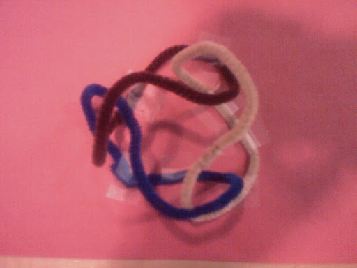
It seems that a Bitter coil is meant to be used with DC according to http://www.oersted.com/magnetizing.PDF so I am guessing that your intent is to use the coil as an anode or cathode as opposed to an AC magnet. In any case I think it is possible to construct the magnet as interlocking Bitter coils as long as you make it in the form of the popular cat toy appropriately called the Nobbly-Wobbly. The cat toy is shown below.

I like this toy very much because this is how I imagine electrons manage to avoid colliding with each other as they travel around the nucleus of an atom. In any case, I think interlocking Bitter coils could be constructed in this fashion.
>But, I can't quite picture how the loom works.<
I am afraid it's not a loom but rather just a simple fixture. I had to take each spool off it's post in sequence and wrap it once around the soccer ball, repeating the process 50 or 100 times until it was done.
The process could be automated but only with a machine that is capable of passing the spools around obstacles. A robot arm would work fine.
The magnet is now in the possession of Chuck Hoberman. I have brought it to various smart people to see if anyone has a use for it. I would be happy to send it to anyone in this forum who thinks it might have a use and wants to test it's properties.
Thanks, John
The way that you are thinking about using the coil arrangement is different than I had anticipated so in order to give you intelligent answers I will need to study the polywell concept for a few weeks. However, I am prepared to give you answers that are not very inteligent right now.
>Can you do it with Bitter Coils? <
It seems that a Bitter coil is meant to be used with DC according to http://www.oersted.com/magnetizing.PDF so I am guessing that your intent is to use the coil as an anode or cathode as opposed to an AC magnet. In any case I think it is possible to construct the magnet as interlocking Bitter coils as long as you make it in the form of the popular cat toy appropriately called the Nobbly-Wobbly. The cat toy is shown below.
I like this toy very much because this is how I imagine electrons manage to avoid colliding with each other as they travel around the nucleus of an atom. In any case, I think interlocking Bitter coils could be constructed in this fashion.
>But, I can't quite picture how the loom works.<
I am afraid it's not a loom but rather just a simple fixture. I had to take each spool off it's post in sequence and wrap it once around the soccer ball, repeating the process 50 or 100 times until it was done.
The process could be automated but only with a machine that is capable of passing the spools around obstacles. A robot arm would work fine.
The magnet is now in the possession of Chuck Hoberman. I have brought it to various smart people to see if anyone has a use for it. I would be happy to send it to anyone in this forum who thinks it might have a use and wants to test it's properties.
Thanks, John
I don't think so. Here's Tom Ligon's ISDC presentation with dodec mockup on p24:Whoever came up with the shape in your first link was wrong. The correct dodecahedron configuration was just like you designed.
http://isdc2.xisp.net/~kmiller/isdc_arc ... ile_id=422
A polywell can't have intersecting magnets. The electrons follow the field lines. It would be like using permanent magnets.
Bussard believed a dodec would give a 3-5x better density ratio, if I'm remembering Valencia correctly. It's probably minimally noticeable at WB-7 size, but at WB-100 size that increased density could help a lot.
-
johnshearing
- Posts: 7
- Joined: Fri Oct 17, 2008 1:32 am
- Location: New York
- Contact:
Hi Solo, tombo, and TallDave,
You're probably already thinking this but I might as well say it out loud.
What about a coil arrangement demonstrated by the cat toy above?
This is the same configuration as the spherical magnet found at the link below.
http://www.justodians.org/SphericalMagn ... agPic1.htm
The only difference is that the coils of the magnet intersect where as in the cat toy, the rings are bent so as to avoid intersection. What if I were to make an electromagnet configured like the Nobbly Wobbly keeping all the coils away from each other with plastic or ceramic spacers? Does this address the issue of field null at the corners? Does this have any use as a polywell?
Also, please notice that the spherical electromagnet and the Nobbly Wobbly configuration both have 12 pentagonal openings evenly spaced around their surfaces. So I can’t help but wonder if 12 windings in the dodecahedral polywell configuration could sit on top of (but not touching) the 6 windings made in the Nobbly Wobbly configuration located by the 12 pentagonal openings. In other words, why can’t a spherical electromagnet sit inside a dodecahedral polywell? Maybe if all the magnetic forces are working together, perhaps this might make for a tighter packing of electrons, which might increase the likely hood of collisions.
Hi jmc,
Thank you so much for forwarding the Keller Jones paper to me.
While I don't pretend to understand the math in the paper I would like to tell you what I perceive to be similar and different about what they were trying to accomplish and how it all might relate to the polywell concept.
Similar:
Using an arrangement of AC coils to create a plasma bottle such that the gaps in the magnetic fields are in constant motion, as is the plasma, with the idea being that the plasma always lags behind the gaps so that escape is impossible.
I Hadn't Thought of This:
While I did mention the possibility of using the spherical electromangnet for forming ball bearings using heat from magnetic induction, I never thought of using AC magnetic fields to create plasma with heat by induction.
Different:
The structure and general shape of the coils are quite different.
Not Sure:
1. While I am interested in exploring the use of alternating current and direct current, I also imagine trying rectified waves as the signal input. This might ensure that the magnets only push in one direction as with DC but also compression would be added. What about square wave pulses both positive and negative timed and distributed to each of the six coils in such a way as to choreograph movement of electrons and ions in and out of the well? Tom Ligon compares the polywell to an engine but an important component of any engine is the timing of compression. If I understand correctly, the object of the polywell is to get electrons and ions to fly through the same space so that collision can occur. Well time is space and so I wonder if the chances of collision increase if we can make the particles intersect in the same place at the same time. These folks talk about something like this.
http://www.polywellnuclearfusion.com/Cl ... /POPS.html
2. It seems Keller and Jones were trying to avoid inducing magnetic fields in the plasma where as I hope to induce magnetic fields with the intention of creating virtual windings within the plasma.
3. I couldn't figure out if Keller and Jones were trying to get the plasma to spin inside the vessel or not, but my hope for the spherical electromagnet is that it will impart spin to the plasma and that the axis of rotation will be in constant change. I have two reasons for wanting to accomplish this.
(A) I have heard that a change in axis of rotation is what creates the enormous pressure inside a tornado. And a tornado has no physical bottle to hold all that pressure (like a plasma bottle). So I am thinking that twisting the axis of rotation in a body of plasma might also increase the pressure. And in a polywell, I imagine that this would create a greater concentration of ions at the center, which increases the chances of collision with electrons passing through.
(B) The effect of plasma spinning in different directions inside the bottle should result in more than one virtual coil. And one virtual coil acting upon another might have the potential to function as a virtual motor where the outer coil causes the inner coil to spin even faster inducing an even stronger magnetic field near the center.
4. I am not sure how much of the Keller/Jones paper I interpreted correctly and I have no idea how much of my own thinking on this matter is pure fantasy. I am a machinist/welder with some electronics education. I am not a physicist. In any case, I have heard it said that a good test is worth 1000 theories. So with guidance from this community I hope to conduct some tests with the intention determining if this particular arrangement of coils has any application to the polywell concept.
Thanks for your help and encouragement,
John
Solo wrote: > I guess this would suffer the same issue as my proposal to join the edges of tombo's single-turn coils: the corners will have a field null.<
tombo wrote: > But, I agree with Solo about the intersections.
Although a very close detailed look at the intersection fields might show some resolution.<
TallDave wrote: >A polywell can't have intersecting magnets. The electrons follow the field lines. It would be like using permanent magnets. <
You're probably already thinking this but I might as well say it out loud.
What about a coil arrangement demonstrated by the cat toy above?
This is the same configuration as the spherical magnet found at the link below.
http://www.justodians.org/SphericalMagn ... agPic1.htm
The only difference is that the coils of the magnet intersect where as in the cat toy, the rings are bent so as to avoid intersection. What if I were to make an electromagnet configured like the Nobbly Wobbly keeping all the coils away from each other with plastic or ceramic spacers? Does this address the issue of field null at the corners? Does this have any use as a polywell?
Also, please notice that the spherical electromagnet and the Nobbly Wobbly configuration both have 12 pentagonal openings evenly spaced around their surfaces. So I can’t help but wonder if 12 windings in the dodecahedral polywell configuration could sit on top of (but not touching) the 6 windings made in the Nobbly Wobbly configuration located by the 12 pentagonal openings. In other words, why can’t a spherical electromagnet sit inside a dodecahedral polywell? Maybe if all the magnetic forces are working together, perhaps this might make for a tighter packing of electrons, which might increase the likely hood of collisions.
Hi jmc,
Thank you so much for forwarding the Keller Jones paper to me.
While I don't pretend to understand the math in the paper I would like to tell you what I perceive to be similar and different about what they were trying to accomplish and how it all might relate to the polywell concept.
Similar:
Using an arrangement of AC coils to create a plasma bottle such that the gaps in the magnetic fields are in constant motion, as is the plasma, with the idea being that the plasma always lags behind the gaps so that escape is impossible.
I Hadn't Thought of This:
While I did mention the possibility of using the spherical electromangnet for forming ball bearings using heat from magnetic induction, I never thought of using AC magnetic fields to create plasma with heat by induction.
Different:
The structure and general shape of the coils are quite different.
Not Sure:
1. While I am interested in exploring the use of alternating current and direct current, I also imagine trying rectified waves as the signal input. This might ensure that the magnets only push in one direction as with DC but also compression would be added. What about square wave pulses both positive and negative timed and distributed to each of the six coils in such a way as to choreograph movement of electrons and ions in and out of the well? Tom Ligon compares the polywell to an engine but an important component of any engine is the timing of compression. If I understand correctly, the object of the polywell is to get electrons and ions to fly through the same space so that collision can occur. Well time is space and so I wonder if the chances of collision increase if we can make the particles intersect in the same place at the same time. These folks talk about something like this.
http://www.polywellnuclearfusion.com/Cl ... /POPS.html
2. It seems Keller and Jones were trying to avoid inducing magnetic fields in the plasma where as I hope to induce magnetic fields with the intention of creating virtual windings within the plasma.
3. I couldn't figure out if Keller and Jones were trying to get the plasma to spin inside the vessel or not, but my hope for the spherical electromagnet is that it will impart spin to the plasma and that the axis of rotation will be in constant change. I have two reasons for wanting to accomplish this.
(A) I have heard that a change in axis of rotation is what creates the enormous pressure inside a tornado. And a tornado has no physical bottle to hold all that pressure (like a plasma bottle). So I am thinking that twisting the axis of rotation in a body of plasma might also increase the pressure. And in a polywell, I imagine that this would create a greater concentration of ions at the center, which increases the chances of collision with electrons passing through.
(B) The effect of plasma spinning in different directions inside the bottle should result in more than one virtual coil. And one virtual coil acting upon another might have the potential to function as a virtual motor where the outer coil causes the inner coil to spin even faster inducing an even stronger magnetic field near the center.
4. I am not sure how much of the Keller/Jones paper I interpreted correctly and I have no idea how much of my own thinking on this matter is pure fantasy. I am a machinist/welder with some electronics education. I am not a physicist. In any case, I have heard it said that a good test is worth 1000 theories. So with guidance from this community I hope to conduct some tests with the intention determining if this particular arrangement of coils has any application to the polywell concept.
Thanks for your help and encouragement,
John
Good creative thinking.
I see a problem with the knobbly wobbly (interesting how many of these models are kid's toys).
Consider one wire crossing point. Simplify it to 2 straight wires crossing at right angles.
Use the RH rule to find the directions of the magnetic fields in each of the quadrants.
Notice that in 2 of the quadrants the fields reinforce but in 2 of them the fields oppose each other.
That means that somewhere in that quadrant there will be a field null.
This is a bad thing.
DrMike pointed this problem out to me when I proposed the cyclone fence coil configuration.
I have not looked closely to see if the extra curves in and out help, but I expect the null will still be in there somewhere. TANSTAAFL
The pressure inside a tornado is negative that's why they suck the roofs off of houses.
Induced current coils in the plasma have been discussed here under "Theory". I don't see where now, but check it out.
There may be some interesting plasma physics in the spinning plasma as a motor/dynamo like the earth's core.
The theory & modeling guys have a hard enough time with even the simplest static models. Look at "virtual polywell" thread for some enlightenment. I can imagine all sorts of distressed noises coming from that camp when asked to expand the models to include dynamo theory.
Check out the thread "theory>magrid configuration brainstorming". I think you would like it. (if you haven't already found it, that is.)
-Tom Boydston-
"If we knew what we were doing, it wouldn’t be called research, would it?" ~Albert Einstein
"If we knew what we were doing, it wouldn’t be called research, would it?" ~Albert Einstein
-
johnshearing
- Posts: 7
- Joined: Fri Oct 17, 2008 1:32 am
- Location: New York
- Contact:
Hi tombo,
I am not interested so much in promoting this coil arrangement as I am in promoting the idea of running a lot of random experiments over as short a period of time as possible. That's the method Edison used to come up with a viable light bulb. Even Dr. Bussard was not able to predict a viable polywell on the first, second, or even the third try. If we all arrived at this place and time through the process of evolution then we ourselves were bumbled into existence. So for earlier success, lets bumble faster. Please understand that I am not advocating for the type of copious experimentation they are doing with tokamaks. They do not seem to bumble so much as plod.
I followed your advice and checked how original spherical electromagnet might behave according to the right hand rule. Of course it all depends on how the current is applied to the six coils and there are an infinite number of ways to do that, but one interesting result is shown below.

The effort making these models has caused me to wonder if this type of coil arrangement lends itself to making logic gates according to the principles of the magnetic amplifier. So I am off to bumble in that direction for a while.
Thank you again for all your help and encouragement,
John
Thank you for guiding me to this thread. I really enjoyed learning about your idea for creating a magrid. I especially appreciated the beautiful computer aided drawings and the way you were able to get your idea across right away.Check out the thread "theory>magrid configuration brainstorming". I think you would like it.
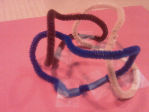
I was under the impression that a field null is bad only if it's located at a coil because this causes a collision between circulating electrons and the coil. This condition occurs when coils touch each other; which explained the problems encountered in the first polywells. But what about the coil shown below which is just a less cluttered Nobbly-Wobbly (shown a few posts up). The coils (below) don't come near each other even though their fields intersect causing nulls. I think these coils are different (and therefore interesting) because they do not follow the surface of a sphere as all the other magrid configurations that I have seen so far seem to do. I don't think the behavior of a polywell built this way can be known for certain without running a test.I see a problem with the knobbly wobbly (interesting how many of these models are kid's toys).
Consider one wire crossing point. Simplify it to 2 straight wires crossing at right angles.
Use the RH rule to find the directions of the magnetic fields in each of the quadrants.
Notice that in 2 of the quadrants the fields reinforce but in 2 of them the fields oppose each other.
That means that somewhere in that quadrant there will be a field null.
This is a bad thing.
I am not interested so much in promoting this coil arrangement as I am in promoting the idea of running a lot of random experiments over as short a period of time as possible. That's the method Edison used to come up with a viable light bulb. Even Dr. Bussard was not able to predict a viable polywell on the first, second, or even the third try. If we all arrived at this place and time through the process of evolution then we ourselves were bumbled into existence. So for earlier success, lets bumble faster. Please understand that I am not advocating for the type of copious experimentation they are doing with tokamaks. They do not seem to bumble so much as plod.
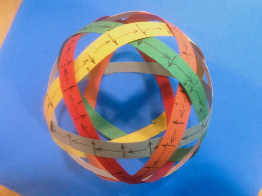
I followed your advice and checked how original spherical electromagnet might behave according to the right hand rule. Of course it all depends on how the current is applied to the six coils and there are an infinite number of ways to do that, but one interesting result is shown below.
The effort making these models has caused me to wonder if this type of coil arrangement lends itself to making logic gates according to the principles of the magnetic amplifier. So I am off to bumble in that direction for a while.
Thank you again for all your help and encouragement,
John
I like the way you have documented the current and B field vectors on the paper tape model.
It shows clearly that I was wrong in my vision of where the fields went.
Oh well there goes another one.
It has been a long time since I used paper dolls to model parts.
That is a time honored engineering technique.
Sometimes we get so stuck in our computers that we forget to use the simpler easier tools.
I think field nulls are bad where-ever they are located.
At least that was what I was told by the more experienced members.
Also the more spherical the fields are, the better, in order to preserve the whiffle ball cusp closing effect.
I keep thinking that there has to be a way to make the fields visible in 3D.
Maybe something like iron filings suspended in vegetable oil.
That way you could see what the fields created by your wire model look like.
-Tom Boydston-
"If we knew what we were doing, it wouldn’t be called research, would it?" ~Albert Einstein
"If we knew what we were doing, it wouldn’t be called research, would it?" ~Albert Einstein
Hadn't someone emailed the webmaster at http://www.falstad.com/vector3dm/ , who replied that he'd add it to his magnetostatics applet?