Indrek,
I believe Dr. B said that the electron predominance was about 1 part in 1E6.
So your 1E5 number is right in the ballpark.
What that also says is that to to keep truncation errors from propagating and seriously affecting the results you need at least 64 bits for the significand possibly more. Of course that is just a WAG. You would have a better idea than I do.
A 64 bit float only has 53 bits for the significand. That is about 16 significant digits. Subtract 6 from that and you get 10 significant digits (based on the difference in electron vs ion charge densities). So now what you need to estimate is the accuracy required and the guard band for truncation errors.
Dr. B says that typical computers are not good enough. What is your estimation? Of course a lot of that depends on the number of iterations you plan to do, the size of your time slices etc.
So the question is what kind of chip are you using and how are floating point numbers handled? An 80 bit floating point unit might be good enough.
What do you think?
In any case I'm excited about all this. Learning stuff on the cheap will give us a clue about the requirements if we ever get a real budget.
Virtual Polywell
As I understand it, that has always been the main problem in simulating a polywell.
I doubt this is a question of floating point precision though.
The problem (for particle in cell approaches) is, if in a electron only simulation we need i.e. 1E5 macro particles to get an acceptable electrical field precision, for electrons and ions we will need those 1E5 for the charge difference alone, thus 2E11 for the whole, which is a lot.
Otherwise the result will be an electrical field consisting mainly of noise.
It might be better if we stick with simpler models, concentrating on different aspects of the polywell.
For example we could try to check the wiffle ball scaling by using a constant electrical field, thus no need to simulate the ions.
Another idea might be to go along the lines of EIXL, only simulate the area inside the wiffleball and assume spherical symmetry. If a good collision model could be developed for this, it might be very insightful.
I'm not sure if they have true 128 bit floating point, but check out the new AMD quad core:
http://developer.amd.com/articles.jsp?id=171&num=2 Seems like it can be used quite effectively for accurate modeling, especially if you vectorize the processing. It would be interesting to program that beast in assembler!
At any rate, the hardware is getting there. In a few months these things should be off the shelf cheap (if not obsolete with octacore's coming next....)
I'm still trying to get one particle right. Good thing knowledge grows exponentially!
I finally got the segments figured out for the 1/48 blocks. I next have to make sure I'm putting them together correctly, but here's the B field "sextant"
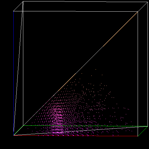
And here is the E field:

It's easy to see why this looks like it will work to zeroth order. You have a strong E field pulling electrons into the center and no force other than self repelling (which is big to be sure) pushing them out. The B field is strong near the coils and weak far away, so again there's little force other than to keep the electrons away from the coils.
Hopefully I can be tracking particles soon....
The red and blue lines are x and z axis, so we're looking into the y axis. I color coded the vectors to help with debugging, red is radius index, green is x,y plane angle, and blue is angle up from the x,y plane.
And here is the E field:
It's easy to see why this looks like it will work to zeroth order. You have a strong E field pulling electrons into the center and no force other than self repelling (which is big to be sure) pushing them out. The B field is strong near the coils and weak far away, so again there's little force other than to keep the electrons away from the coils.
Hopefully I can be tracking particles soon....
The red and blue lines are x and z axis, so we're looking into the y axis. I color coded the vectors to help with debugging, red is radius index, green is x,y plane angle, and blue is angle up from the x,y plane.
I've tried to figure out better ways of doing things but it's going slow. Here's where I am right now:
http://www.mare.ee/indrek/ephi/wb1/ (warning, lots of images)
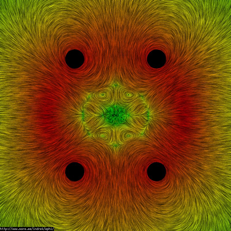
I think the field within the magnetic ball should be close to zero, maybe that's the reason I don't see much confinement here right now. Also I probably need tools to gauge particle densities better.
Currently I'm using a quite primitive way to calculate the fields. There is room for improvement though but ultimately it may turn out to be a failure. Will see.
I should try to develop some PIC code to see how that works later on.
- Indrek
http://www.mare.ee/indrek/ephi/wb1/ (warning, lots of images)
I think the field within the magnetic ball should be close to zero, maybe that's the reason I don't see much confinement here right now. Also I probably need tools to gauge particle densities better.
Currently I'm using a quite primitive way to calculate the fields. There is room for improvement though but ultimately it may turn out to be a failure. Will see.
I should try to develop some PIC code to see how that works later on.
- Indrek
There is ZERO field at the center - your calculations are correct. There should be a particle self field though, and you will see it with a PIC code.
This is great stuff! If several different models give similar answers, we'll have some high confidence it works.
It always appears to be slow going when you are in the drivers seat. Looks to me like you are doing really well - I know I'm going a low slower than I want to!!
This is great stuff! If several different models give similar answers, we'll have some high confidence it works.
It always appears to be slow going when you are in the drivers seat. Looks to me like you are doing really well - I know I'm going a low slower than I want to!!
I put my code up for the E and B fields here:
http://www.eskimo.com/~eresrch/Fusion/spfieldgen.c
I'm pretty sure it's right now, but I'm still checking my look up methods. The plot routine is in the same directory under file name "plotfield.c". It is a snap shot of "living code", which means I don't see the bugs because it is changing so fast
There are a few people here who can improve this code tremendously. I think having the coil radius and max wall distance be inputs so different configurations can be easily (and rapidly) checked would be a great idea. Right now I let my code run over night, but I think it "only" takes 3 hours to create the data. It's not bad for how much data and what it comes from, but it sucks for trying to check lots of different mechanical configurations.
I gotta admit this is really fun though...
Speaking of fun, here's a complete and total mistake:

I thought it was pretty, but my wife disagrees
Here's a plot of the E field using Indrek's 1/48 and spherical compression:

And here's the B field with the same method:

Both images are looking into a corner cusp with an average over 4x4x4 nearest points.
I bet my particle tracks will still have bugs, but with luck I'll eliminate them soon![/url]
I thought it was pretty, but my wife disagrees
Here's a plot of the E field using Indrek's 1/48 and spherical compression:
And here's the B field with the same method:
Both images are looking into a corner cusp with an average over 4x4x4 nearest points.
I bet my particle tracks will still have bugs, but with luck I'll eliminate them soon![/url]
I did have one major bug, but now they must be subtle ones. Here are two plots, both are in velocity dimensions rather than space. The initial velocity is out the cusp, and is set to about .03 * grid voltage in each of x, y and z directions. In the first plot, the grid is set to 10,000 V and in the second it is set to 50kV. For both the current in the coil is set to 200,000 Amp-turns. All calculations are done dimensionlessly though, so take it as scaled rather than useful numbers.
Velocity plot 1:

Velocity plot 2:

It looks like collisions are going to be really important, especially when things get to the turning points in the orbits. The lower grid voltage had better confinement, so the ratio of amp-turns to grid voltage is leaning towards higher current. At this point I'd say so what - not enough data, but interesting all the same.
More fun to come, but I gotta get some sleep for the day job...
Velocity plot 1:
Velocity plot 2:
It looks like collisions are going to be really important, especially when things get to the turning points in the orbits. The lower grid voltage had better confinement, so the ratio of amp-turns to grid voltage is leaning towards higher current. At this point I'd say so what - not enough data, but interesting all the same.
More fun to come, but I gotta get some sleep for the day job...
I don't really understand very well on what I'm seeing but it looks nice.
About calculation speed. For me it takes just a few seconds to calculate a 100MB grid. This is thanks to using analytic forms (and in part to my quad-core Intel system). If you don't trust my sources you can try the Dolan's book:
http://www.fusionnow.org/dolan.html
Chapter 20, equation 20B14 - b-field of a circular current element. The elliptic integrals are available in the libgsl you are using. You'll get a 20-40 times increase in speed and also better accuracy.
I'm not sure on what you are using for the electric field - but if it's a circular electric charge then I've developed equations for that as well:
http://www.mare.ee/indrek/ephi/efield_r ... charge.pdf
Being able to get results quickly will help tremendously with your work - you can try out different things without having to wait hours or even getting a coffee.
- Indrek
I've been thinking about the plots this morning. It tells me that the basic configuration is not stable - the E field continuously adds energy to the electrons. The magnetic field does help containment, but just having the MaGrid positive and the outer shell ground isn't good enough.
Continuous oscillations are probably a good thing for long confinement times. I'm going to think about ways to do that, and to look at other E field configurations. There is a grid in the pictures of WB-6, anyone know what voltage that was at relative the MaGrid? I'll also look at changing the outer wall from ground to negative.
I'd like to make note of the connection between the single particle motions and the forces on a fluid model. It is exactly the same formula. An understanding of simple stuff leads to a good idea on how the messy stuff will behave too.
I forgot to post the particle tracking code last night - I will try to do that tonight. It'd be nice if anyone can point out bugs in that code too!
Thanks Indrek! I will go check that stuff out. I looked at Jackson for a current loop, but figured brute force would be simpler. 20 to 40 times faster is a good reason not do do that!