If computer modeling, mathematical evaluations alone are not science, then there are a lot of university Physics and mathematics departments that are playing. Certainly String theory and derivatives fit in this catagory. The hunt for the Higgs particle thus far fits in this category (at least in a strict sense).
Computer modeling or mathematical formula are no different than a verbal hand waving description of a system. But, they do (if used properly and not messed up or improperly applied) allow for a more precise and consistent description. They might or might not allow for better predictability. All of this is indeed just descriptions and does not create reality, except for some Sci Fiction stories where the Mathematician/ Wizard quotes a formula to enact a spell.
As far as the magrid design, when I draw current lines on it, the large squares and triangles seem to act like point cusps. The small squares look like funny or abreviated line cusps. I think they may have a total metal- cusp exposure comparable to the nubs where they connect to each magnet in WB6. The unshielded area may be smaller though as the arms of these 'nubs' are shielded. Also the collection areas that drain into these small and high B flux areas may result in fewer electrons entering these cusps. How the final balance would work out is beyond me. Mathematical modeling or experiment, either one, would give a more confident answer .
Dan Tibbets
magrid configuration brainstorming
Computer modeling and mathematics can only help to make a theoretical calculation; it's not a firm Theory until it has actual physical evidence, from an experiment designed to test the theory.D Tibbets wrote:If computer modeling, mathematical evaluations alone are not science, then there are a lot of university Physics and mathematics departments that are playing. Certainly String theory and derivatives fit in this catagory. The hunt for the Higgs particle thus far fits in this category (at least in a strict sense).
But Kiteman ws just saying "this is so, prove me wrong"
And that ain't science.KitemanSA wrote:I've done it at the rigour I needed. You are carping about it, you prove me wrong.
It would be science if KitemanSA had posted a magnetic field map of the "pretty" model. Just making a "pretty" model and saying it would be better is NOT science.
But I doubt his CAD skills extend into the realm of a FEA of the magnetics around a complex 3D multi-solenoid system, filled with a cloud of warm electrons.
Wandering Kernel of Happiness
My mental gymnastics issue is where the single coil can splits apart to form the seperate legs (one for the square, one for the triangle).
Picture the pointy square formed by the two squares and triangles, imagine it has a flat (actually bowed in) edge on the bottom, top and left and right. The Triangles are on the bottom (pointing up) and top (pointing down).
For arguments sake, say the current flows towards the square center from the bottom right "split". So one flow goes left to right along the bottom edge and then turns away and down on a departing leg, the other flow goes from bottom to top on the left edge and then turns away to the left and up on another departure.
This means that the top edge would have to flow from right to left, and the right edge would have to flow top to bottom.
My issue lays in a insecurity on how the field would develop given this at the top left and bottom right corners, or the current flow exit points from the "small bowed in square".
I would think that in order to be effective for shielding, the current should loop around the perimeter of the small bowed in square, in the same manner it does with a large one or triangle. I do not see where this is possible. I also think that the merging current flows at the exit points would make for a not so optimum field cusp.
Help me out here, it is really hurting my head.
In all cases, the field will be modified from the basic circle with conductor in the center. But if you split the current, each branch, of necessity, will have less magnetic field.ladajo wrote:My mental gymnastics issue is where the single coil can splits apart to form the seperate legs (one for the square, one for the triangle).
That, however, is not the primary problem. If you want a good "Whiffleball trapping factor" the holes in your whiffleball must be as small a percentage of the total area inside as possible. This is because scattering events will realign electrons in their placid orbits around the core, and you want as few of those as possible to scatter into an outgoing cusp. You want to maintain as high as possible the electron density in the middle of your polywell.
Wandering Kernel of Happiness
An electron will orbit from North pole to South pole, along a magnetic field line. So, you want the North poles to have much more area than south poles.ladajo wrote:Can I take it that you are advocating a six coil cube with standoffs as the best minimalist approach?
And my question remains, what is the effect of a square with two opposing current entries and exits? In my head it comes out as an elongated cusp, that may expose metal.
But, if you have a hole in your grid with some conductors around it going one way, and others going the opposite way (as viewed from outside) then there is NO pole; that is, the magnetic fields have canceled in at least part of the hole. And that is a cusp, in a nutshell.
The "line cusps" in WB-6 were where the cube edges were, the "funny cusps" where the corners were. You can squash the coils into more squarish shapes, or add more coils, in order to LIMIT these, but they cannot be removed (unless you figure out how to make a magnetic monopole).
Does that clear things up some?
Wandering Kernel of Happiness
Mmm, yes. I have done the math. I have presented the math. If you disagree with the math, YOU show ME.WizWom wrote:Um, NO.KitemanSA wrote:I've done it at the rigour I needed. You are carping about it, you prove me wrong.icarus wrote: Do it yourself. It is your brilliant idea after all.
I have proved my design more rigorously than any other except the WB 6&7, and even EMC2 thought there were problems with them. Where is lack-wing's demonstrated design? Anything? No? Carping.WizWom wrote: This is science, not law. You need to Prove your theory or design rigorously, with either a demonstration or mathematics.
And a mathematical proof needs to have a physical demonstration for it to be acceptable.
The math has been done. The math as I understand it says it is protected. Carp all you want about it, but until you provide either the math or the demonstration that it is wrong, you are just carping. Carp away!WizWom wrote: Thank you for playing, please go back to freshman Physics before trying again.
Hey, if you wish to challange it, do so. But apply at least the rigour to your challange as went into the original statement. I backed mine up with math. Until you do the same, it is NOT a challange, it is useless carping. I welcome a challenge. I "spit in the general direction" of carping!icarus wrote:Nice, anybody who challenges your design speculations is "uselessly carping" ...You are carping about it, you prove me wrong. else you are just uselessly carping.
If that was indeed all I did, I would perhaps agree with you, but you are new here. Please go back and investigate what I have published on this board. I have DONE the math. I have published it. It supports my contentions. Until you can show me where my math is wrong, you are just carping... or in your case, perhaps just ignorant of the facts.WizWom wrote: Computer modeling and mathematics can only help to make a theoretical calculation; it's not a firm Theory until it has actual physical evidence, from an experiment designed to test the theory.
But Kiteman ws just saying "this is so, prove me wrong"And that ain't science.KitemanSA wrote:I've done it at the rigour I needed. You are carping about it, you prove me wrong.
I have posted exactly that. Have you? Has lack-wing? No? Carping.WizWom wrote: It would be science if KitemanSA had posted a magnetic field map of the "pretty" model. Just making a "pretty" model and saying it would be better is NOT science.
You would be wrong on the first phrase and right on the second, though according to Dr.s B. & N. the electrons only help improve the field protection by squeezing of the cusps. I did the 3D field model (only of the X cusp in question, the rest was of little interest) which you would know if you had read my earlier posts without prejudice that I am a CAD (WizWom wrote: But I doubt his CAD skills extend into the realm of a FEA of the magnetics around a complex 3D multi-solenoid system, filled with a cloud of warm electrons.
Last edited by KitemanSA on Tue Sep 28, 2010 1:24 am, edited 2 times in total.
Kind of like this? Greys (1, 3) are the triangles, whites (2, 4) are the squares.ladajo wrote: My mental gymnastics issue is where the single coil can splits apart to form the seperate legs (one for the square, one for the triangle).
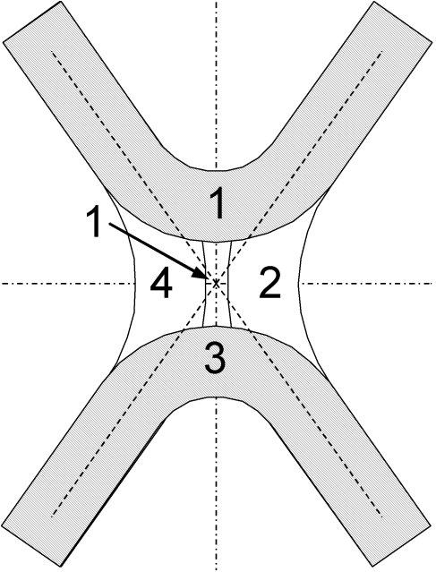
That pointy square is called an X-cusp.ladajo wrote:Picture the pointy square formed by the two squares and triangles,
You seem to change horses in mid-flow here. If the current comes in from the bottom right (2, 3) it splits right to left thru the bottom (3) and bottom to top on the right (2). Ok?ladajo wrote:imagine it has a flat (actually bowed in) edge on the bottom, top and left and right. The Triangles are on the bottom (pointing up) and top (pointing down).
For arguments sake, say the current flows towards the square center from the bottom right "split". So one flow goes left to right along the bottom edge and then turns away and down on a departing leg, the other flow goes from bottom to top on the left edge and then turns away to the left and up on another departure.
At the same time, current is coming in from the upper left and going l/r thru the top and t/b thru the left.
Again, backward?ladajo wrote: This means that the top edge would have to flow from right to left, and the right edge would have to flow top to bottom.
In from the upper left and lower right, out thru the lower left and upper right. (1+4 and 2+3 > 1+2 and 3+4)ladajo wrote: My issue lays in a insecurity on how the field would develop given this at the top left and bottom right corners, or the current flow exit points from the "small bowed in square".
What it seems you want is for the cusp at that center point to be a point cusp. But it is not. It is a funny cusp without metal in the middle, i.e., an X cusp.ladajo wrote: I would think that in order to be effective for shielding, the current should loop around the perimeter of the small bowed in square, in the same manner it does with a large one or triangle. I do not see where this is possible. I also think that the merging current flows at the exit points would make for a not so optimum field cusp.
This is a plot of the tangential field generated by the WB6 (line-like cusp - right panel), the patented Polywell (funny cusp - left panel) and the figure you saw in the earlier post (X cusp - middle panel).ladajo wrote: Help me out here, it is really hurting my head.
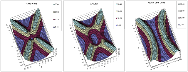
It has been a while so I am not quite sure how far inside the coils this plane was taken, but over MOST of the pale blue areas, the tangential field is strengthened by the wiffle-ball effect (not shown) except in the cusps. In the cusps, the areas get squeezed in from the sides a bit, but don't raise in tangential strength at all. Since it is the tangential strength that reflects the electrons, it is the TS that protects the metal, and ALL the metal in the Xcusp is covered with high TS. The WB6 has a nub thru the middle of the line-like cusp, and the patented Polywell has metal in the center of the funny cusp.
Last edited by KitemanSA on Tue Sep 28, 2010 1:26 am, edited 1 time in total.
What? "Placid orbits around the core"? The electrons are bouncing back and forth across the core as reflected by the quasi-spherical magnetic field. No amount of "up-scattering" is needed to put them out the cusps if their bouncing around gets them properly lined up. They are going like a bat out of heck (WizWom wrote: That, however, is not the primary problem. If you want a good "Whiffleball trapping factor" the holes in your whiffleball must be as small a percentage of the total area inside as possible. This is because scattering events will realign electrons in their placid orbits around the core, and you want as few of those as possible to scatter into an outgoing cusp. You want to maintain as high as possible the electron density in the middle of your polywell.
WizWom wrote:An electron will orbit from North pole to South pole, along a magnetic field line. So, you want the North poles to have much more area than south poles.ladajo wrote:Can I take it that you are advocating a six coil cube with standoffs as the best minimalist approach?
And my question remains, what is the effect of a square with two opposing current entries and exits? In my head it comes out as an elongated cusp, that may expose metal.
But, if you have a hole in your grid with some conductors around it going one way, and others going the opposite way (as viewed from outside) then there is NO pole; that is, the magnetic fields have canceled in at least part of the hole. And that is a cusp, in a nutshell.
The "line cusps" in WB-6 were where the cube edges were, the "funny cusps" where the corners were. You can squash the coils into more squarish shapes, or add more coils, in order to LIMIT these, but they cannot be removed (unless you figure out how to make a magnetic monopole).
Does that clear things up some?
My understanding is different.
An electron that is traped on a magnetic field line for a partial or multiple gyro orbits will generally start out in a Northerly direction (depending on the field entry vector). But this applies only to the first spiral, drift, deviation(?). Once it reverses it is going South, etc., etc... If the electron is bouncing back and forth perhaps thousands of times before it is transported through the magnetic field, or escapes through a cusp without recirculation, or hits an unshielded support the initial deflection becomes irrelevant. Thus Bussard's comment that it didn't matter whether the N or S poles faced in, just so long as they were consistant.. Secondly, with the near spherical (hopefully) strong B field surface/ gradient at the Wiffleball border, initially, most electrons will rebound from the surface (complete ~ 1/2 gyro orbit/ oscillation before reentering the B field free Wiffleball interior at a small North angle from its entry vector. Ideally, most of the electrons will spend most of their lifetime in this mode. How the dynamic picture of these two populations of electrons change over the lifetime of the electron is a mystery for me.
The cusp names have been confusing for me. I initially thought the corner cusps were funny cusps. But, partially from the 2008 patent application, I think Bussard may have been referring to the funny cusps as the 0 strength B-field between magrid coils that were assumed to be infinitely thin, and infinitely close to each other in the simulations. With discussions of virtual grids at the corners and his discriptions in the patent application, I think the corner or edge cusps were considered to be point like cusps. Not as good as real point cusps, but much better than line or equatorial cusps. The assumed infinitely thin 'Funny Cusps' bacame a problem when real finite sized coils were incorperated, especially with the seperation of the coils to permit recirculation (and to prevent too rapid transport of these electrons to the magrid walls in this narrow space. These funny cusps were now more like line cusps, but the recirculation thus allowed made them much more forgiving- except for those pesky exposed nubs!
Your discription of the small square 'interconnects' fits my understanding. The major difference compared to WB6 interconnects (nubs) is that most of the area of these interconnects are magnetically shielded, with only the corners exposed by the magnetic field geometry (pinches?). This may expose much less surface area compared to WB6 nubs, so while they are an exposed surface, compared to WB6 it is a lot less. Perhaps to such a large degree that they represent a loss area of ~ 1/100,000th to ~1,000,000th, instead of the target minimum of ~ 1/10,000 to 1/ 100,000th.
This proportionately smaller exposure may be quite acceptable, and they would help to make a nice rigid and strong structure. What I wonder about is the engineering difficulty of getting good controlled coolant flow through all the twists, turns, and branches. Also, the entire magnet assembly would need to be cooled with one (or several coolant flows with even more complicated plumbing) at proportionately higher coolant flow rates to carry away all the heat.
That is why I naively assume that separate assemblies for each magnet is superior. More difficult to engineer the necessary support strength, but much easier to cool. Generally, if the system works at all, it seems that the thermal load limits on the (superconducting) magnets will be the limiting factor that determines useful sizes. I suspect the issue of using mostly shielded interconnects or separate mostly shielded standoffs may be a wash.
Dan Tibbets
To error is human... and I'm very human.
Actually, I believe that both of you are essentially describing the same thing with different words. I assume WizWom is referring to transverse scattering as opposed to only up or down scattering.KitemanSA wrote:WizWom wrote: That, however, is not the primary problem. If you want a good "Whiffleball trapping factor" .......
What? "Placid orbits around the core"? The electrons are bouncing back and forth across the core.......
Dan Tibbets
To error is human... and I'm very human.
Wrong.ALL the metal in the Xcusp is covered with high TS
Where the current-carrying cans split the magnetic fields dictate that at some point on the surface the fields strength is a null, zero, zip ... i.e unprotected.
Your beautiful FEA analysis is bogus if it did not pick up that obvious, unavoidable topological feature of the field, i.e. the field cannot be going in two opposite directions at the same point on the surface ... or maybe they can in kite-boy world?
Fraud or just ignorant carping?