rjaypeters wrote:"Straight" Square 6, 7?:
...
Probably a lot less trouble to build than the "bowed" variety.
Those are Dr. B's "square planform" WB7. There may be situations (winding needs) that make the bowed version easier to wind than the straight. But even where it isn't, it need never be much more difficult.
The only real question should be is it sufficiently beneficial to warrent any minor increase in cost? TBD.
Seems unlikely to create a wiffle-ball. The wiffle ball has a vast area of transverse field and only small points (unwanted slits in the case of WB6) of exiting field.
This looks like it would have vast channels rent thru the transverse field leading many electrons astray. Not really a wiffle-ball.
Sounds like some more emotive gobble-de-gook "vast areas".... "rent channels" ..."electrons going astray" ... got any quantitative analysis to post in the "Theory" section?
Saving that you might have a calling in journalism.
Seems unlikely to create a wiffle-ball. The wiffle ball has a vast area of transverse field and only small points (unwanted slits in the case of WB6) of exiting field.
This looks like it would have vast channels rent thru the transverse field leading many electrons astray. Not really a wiffle-ball.
Just MHO.
I thought the idea of squaring out the coils like in that picture was to reduce the "size" of the funny cusps in the corner? It would increase the lengths of the line cusps between coils, but to me it would seem to decrease the overall cusp area, which should thus decrease losses/increase confinement (assuming I'm understanding the theory correctly).
That is my impression. The funny cusps are arbitrarily defined as the space between two coils, while a corner cusp is the space between three adjacent coils. My contention is based on general considerations of the geometry of these arbitrary regions. Actually, these cusps are continuous. At the corners the spacing between the coils is increased, thus weaker fields and wider cusps. That there are three magnetic coils pushing against this area instead of two mitigates this somewhat, but considering the inverse square law, I doubt the corner cusp can match the funny cusps. Certainly in the conceptual models Bussard used, where the distance between the coil edges in the funny cusp regions was infinity small. With spacing to allow for recirculation, the funny cusps are wider, but the corner cusps are also wider. Trading off longer funny cusps for smaller area corner cusps, especially as this will increase the field strength in most of the corner cusp region should decrease the net losses if my assumptions are correct (that corner cusp losses dominate. It is a trade off, the gains may be modest, tiny, balanced or worse, depending on your assumptions.
Also, playing with permanent magnets in my demo fusor shows the brightest glow, mostly in the corner regions. Lining up the viewing angle so that I am looking straight across two adjacent corners and the corresponding funny cusp (so there is no parallax) shows a brighter line, but this is the addition of the funny cusp and both corner cusps. This is a small area (in width) compared to the roughly triangular area of glow in the corners. I interpret this as an advantage for the funny cusp region due to the narrow width in this area.
The drawing of rounded corner square grids by rjaypeters could be placed closer together to better represent the length of the funny cusps vs their possible width. Also, in his drawing, there are lines transecting the grids, where his curves start and end. This straight line bordered space is what I consider the funny cusp. All of the space where there is curvature of the three opposing grids represents the corner cusp. How close you can approach the corner before adding curvature is is important and limited by engineering and arcing considerations.
Using a definition of a corner cusp as the area that can be enclosed by a circle that intercepts all three magnets fits a concept of a virtual point cusp better (though there are still three line cusps merging to form this cusp. This would decrease the relative borders of the region defined as the corner cusp vs. the funny cusps that are flaring out (widening) as they enter this region. So the answer may be different because the rules are different (comparing apples to oranges). With circular coils, my first discription of corner vs funny cusps would imply that the corner cusp occupies nearly all of the region and funny cusps are of ~ zero length. With square coils with acute 90 degree turns at the corners, the funny cusps are almost the entire area, while the corner cusps are near zero area, based on my second definition. The only accurate measure is consider the total area between the magnet edges and throw in a fudge factor for the seperation of the magnets integrated over the entire lengths. Then possibly have an additional fudge factor where the interacting fields from three magnets dominate over the effects seen where the fields betweentwo magnets dominate. Not an easy model to analyze.
I may try some photometry measurement in several planes that might illuminate the picture somewhat.
my understanding is that a "funny cusp" refers to what i would call a "saddle cusp" because it looks like [url=http://en.wikipedia.org/wiki/Saddle_point]this[url]. so there are three cusp types: point (roughly z=x^2+y^2), line (roughly z=x^2, y = 0) a, and saddle (aka "funny") (roughly z=x^2-y^2). those represent all of the morphologically distinct possibilities for "cusps" in 3 dimensions.
D Tibbets wrote:The drawing of rounded corner square grids by rjaypeters could be placed closer together to better represent the length of the funny cusps vs their possible width.
You, collectively, may have noticed the random thickness/length ratios of coils I have modeled. Only in older posts* have I read of someone modeling superconducting coils in attempted realistic structures (SC coil, steel, vacuum, steel, helium, steel, etc. or something like that). In fact, I've been waiting for a complaint (though D Tibbets didn't).
I would purely love to scale my models to something realistic. Please, what is a realistic thickness for our SC coil (including structure and coolant flows)?
Should I been using a 1 meter diameter, 1 meter radius or something else for the coil centers?
What spacing should the coils have? I read about electron gyroradii as the determinant, but how does that translate into engineering units, like meters?
Sincerely,
Robert
*But I don't think that poster is currently active.
rjaypeters wrote:I would purely love to scale my models to something realistic. Please, what is a realistic thickness for our SC coil (including structure and coolant flows)?
My memory says the (mostly) agreed upon diameter of the coils was approximately 20 cm (8 in) for the entire coil+coolant+structure.
Lets see, based on some measurements of photos. WB 4 had a minor radius of ~ 25% of the major radius, WB 6 had ~ 17%. So a 20% figure of 20cm/100 cm. is a reasonable ratio. I figure that a minor radius of ~ 33% may be near the maximum useful. This would allow more volume for windings and insulation, etc. It would increase the central point cusp B- fields. The down side is that it may add more cross field transport(?), and more intercept for x-rays or neutrons.
icarus wrote:Sounds like some more emotive gobble-de-gook "vast areas".... "rent channels" ..."electrons going astray" ... got any quantitative analysis to post in the "Theory" section?
Saving that you might have a calling in journalism.
Got it. In icarusese, descriptive = emotive. Thank you.
Seems unlikely to create a wiffle-ball. The wiffle ball has a vast area of transverse field and only small points (unwanted slits in the case of WB6) of exiting field.
This looks like it would have vast channels rent thru the transverse field leading many electrons astray. Not really a wiffle-ball.
Just MHO.
I thought the idea of squaring out the coils like in that picture was to reduce the "size" of the funny cusps in the corner? It would increase the lengths of the line cusps between coils, but to me it would seem to decrease the overall cusp area, which should thus decrease losses/increase confinement (assuming I'm understanding the theory correctly).
Nope, Dr. B's "square plan form WB7 looks like this.
Minus the pretty colors!
By the way, the "funny cusp" is NOT at the corner of the cube. It is where the slightly rounded squares come closest together in this image.
WB6 hade line like cusps where the funny cusps would have been in the patented cuboctahedron.
D Tibbets wrote:That is my impression. The funny cusps are arbitrarily defined as the space between two coils,
Dan, for shame!
The funny cusp is NOT the space between two coils. It is the POINT where an even number (4 or more) of alternating FIELDS meet. WB6 didn't really have any. It had line like cusps instead. The "square plan form design shown in my last post is espected to shorten the line like cusps and make them more like funny cusps.
The cusps in the middle of the triangular places are point cusps (though perhaps distorted ones due to the concave sides) like the middle of the circles.
happyjack27 wrote:my understanding is that a "funny cusp" refers to what i would call a "saddle cusp" because it looks like [url=http://en.wikipedia.org/wiki/Saddle_point]this[url]. so there are three cusp types: point (roughly z=x^2+y^2), line (roughly z=x^2, y = 0) a, and saddle (aka "funny") (roughly z=x^2-y^2). those represent all of the morphologically distinct possibilities for "cusps" in 3 dimensions.
You know, I don't really know the morphology of a funny cusp except that it has been describes as a point of zero field with zero radius.
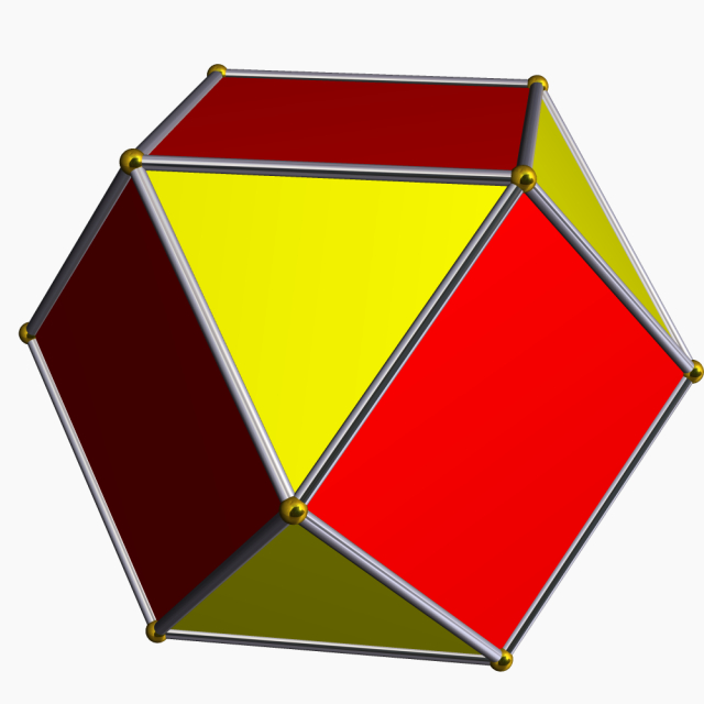
Imagine a WB that looked like this cuboctahedron. The red faces are square magnet coils (silver bars) of zero minor radius with the same polarity pointed inward. The yellow triangles would be virtual magnets with that polarity pointed OUT. Every vertex (gold balls) on that figure would be a funny cusp. In the middle of each face would be a point cusp. THAT IS IT for a "true" polywell. But magnets can't be made with zero minor radius and WB6 proved that the coils shouldn't touch so the closest we can get to this figure is the one I posted about two posts back.
rjaypeters wrote: I would purely love to scale my models to something realistic. Please, what is a realistic thickness for our SC coil (including structure and coolant flows)?
MSimon did a pB&J design with ~1.5m major radius and the SC core was 29cm square, IIRC. At the time, there was expected to be a significant alpha flux into the coils so a multi-stage thermal protection system was anticipated. Since then it has become the understanding that the alphas would tend to exit the cusps, so the TPS may be able to be much smaller. However, no-one has done a new design AFAIK.
Also, MSimon now seems to be of the opinion that for a given SC matrix, smaller is better. He may be right.