Page 8 of 11
Posted: Wed Feb 17, 2010 10:20 pm
by KitemanSA
ladajo wrote:Wall Mounted coils = No nubs between coils.
True, but lots of leakage paths for the HV charge on the MaGrid. I personally prefer the self supporting unit with minimal service connectivity.
This is the type of argument that the engineers will have when the dollars hit the development team.

Posted: Thu Feb 18, 2010 12:38 am
by ladajo
I have been giving the HV leakage issue thoughts as well. If we can come up with some type of not-so-outgassy ceramic laminate construct, coupled with the the stands being in the shadow of the coils, thus minimizing or eliminating contamination being embedded/created by bombardment over time, it might well work nicely.
I've worked with line power up to 22KV directly and know all to well its sensitivity to impurities in the insulators. I've seen a couple of plasma balls eat some hardware, always humbling and spectacular at the same time. It has definitely satisfied my boyish need to blow shtuff up!
Posted: Thu Feb 18, 2010 4:23 am
by mvanwink5
ladajo re:
"I've seen a couple of plasma balls eat some hardware, always humbling and spectacular at the same time."
Yes, always humbling and awesome.
It seems to me the ceramic insulators would be suitable as they were used as bottom supports for WB6. What else could be used? If there is an issue of insulator degradation over time, then just periodically replace them.
Posted: Thu Feb 18, 2010 6:50 am
by Heath_h49008
Ok... lets build one.
We need a dozen research grade 50-60 Tesla MRIs to pull apart, a tank the size of a small living-room, pumps, enough batteries to light up a medium size city, some very high end power management equipment... electron guns, ion management hardware, a full machine shop, some microwave emitters...etc, etc, ad infinitude, ad nausidude...
I'm joking. (sort of) But really, this isn't a lot of gear.

Anybody have friends in a major university science department, or know the door code to some abandoned places like Jackass Flats?
Posted: Thu Feb 18, 2010 8:18 am
by MSimon
ladajo wrote:I have been giving the HV leakage issue thoughts as well. If we can come up with some type of not-so-outgassy ceramic laminate construct, coupled with the the stands being in the shadow of the coils, thus minimizing or eliminating contamination being embedded/created by bombardment over time, it might well work nicely.
I've worked with line power up to 22KV directly and know all to well its sensitivity to impurities in the insulators. I've seen a couple of plasma balls eat some hardware, always humbling and spectacular at the same time. It has definitely satisfied my boyish need to blow shtuff up!
Coating the insulators in order to prevent hot spots (embedded ion concentrations etc. sometimes seen in the old tube days) has been suggested. The more even you can keep the field gradient the better.
Posted: Thu Feb 18, 2010 8:43 am
by MSimon
Heath_h49008 wrote:Ok... lets build one.
We need a dozen research grade 50-60 Tesla MRIs to pull apart, a tank the size of a small living-room, pumps, enough batteries to light up a medium size city, some very high end power management equipment... electron guns, ion management hardware, a full machine shop, some microwave emitters...etc, etc, ad infinitude, ad nausidude...
I'm joking. (sort of) But really, this isn't a lot of gear. :wink:
Anybody have friends in a major university science department, or know the door code to some abandoned places like Jackass Flats?
Research Grade MRIs are coming in at 9T. Production units are heading towards 3T and the most powerful full body MRI is in the 10T to 11T range. The 1T units are being retired.
Posted: Thu Feb 18, 2010 9:09 pm
by Heath_h49008
What do we need for output to support the B-field for pB&j?
I know this thread was based on the idea we need varied strengths for each shape...
But for the hypothetical round magnet with the 15cm hole, and boron... what do we need?
Posted: Thu Feb 18, 2010 11:09 pm
by MSimon
Heath_h49008 wrote:What do we need for output to support the B-field for pB&j?
I know this thread was based on the idea we need varied strengths for each shape...
But for the hypothetical round magnet with the 15cm hole, and boron... what do we need?
For that small a hole 3T is the transition point. About 9T would be good. Fortunately the smaller the dia the larger the field (up to the SC limits).
Posted: Fri Feb 19, 2010 10:13 am
by KitemanSA
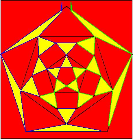
KitemanSA wrote:Marvelous! Yes the MPG is the cuboctahedron.
Please note that your cuboc projection has about the same amount of linage on each wing. Is it easy for you to redo the icosadodec to have the same characteristic?
Never mind, here it is!
Posted: Fri Feb 19, 2010 6:14 pm
by KitemanSA
MSimon wrote:What am I missing?
BTW it is going to be tricky to wire that up with superconductors.
MSimon and I have had this polite disagreement going for some time now, so I figured I'd make another installment!
The winding of the MPGIcos should be insubstantially harder than the MPG, and that would be fairly easy if you plan it right.
Of course it would be easier if you could get the SC tape manufacturers to make a slightly curved tape (think slinky). Then you could get a bow-legged MPGIcos with a fair degree of ease!
The diameter of the slinky tape should be the diameter of the MaGrid. There, I've given away the secret!
Posted: Sat Feb 20, 2010 2:14 am
by hanelyp
MSimon wrote:Research Grade MRIs are coming in at 9T. Production units are heading towards 3T and the most powerful full body MRI is in the 10T to 11T range. The 1T units are being retired.
Which suggests recycling older MRI units into a lab grade polywell.
Posted: Sat Feb 20, 2010 8:07 am
by MSimon
hanelyp wrote:MSimon wrote:Research Grade MRIs are coming in at 9T. Production units are heading towards 3T and the most powerful full body MRI is in the 10T to 11T range. The 1T units are being retired.
Which suggests recycling older MRI units into a lab grade polywell.
We looked into that in an older thread. If you could just buy the magnets without the electronics it might be a good thing.
OTOH relaxed tolerances for winding Polywell magnets allow you to get new 3T magnets for 2X the price of used 1 T MRI Jobs.
Posted: Sat Feb 20, 2010 10:04 am
by MSimon
Kiteman,
A slinky is wrong. The fields will be pointing the wrong way. IIUYC.
And then the mechanical design to resist the generated forces. Lits of nubs or a porcupine of braces to the walls.
Posted: Sat Feb 20, 2010 12:47 pm
by KitemanSA
MSimon wrote:Kiteman,
A slinky is wrong. The fields will be pointing the wrong way. IIUYC.
"IIUYC"??

And then the mechanical design to resist the generated forces. Lots of nubs or a porcupine of braces to the walls.
The slinky is the starting material, not the final product. And when wound into an MPGIcos on it's winding jig it is a self supporting monocoque that needs only be hung by the minimum support to provide against gravity and other externally applied accelerations, and to provide the minimum services (current, cooling...). It works nicely, think about it. You'll catch up!
By the way, remember that I have maintained that the proper MPG needs to be wound in strata that get shifted around the core to create "holey X-Cusps". (Actually, I took to calling those X_MPGs didn't I. This may have added to the confusion. The picture I provided would be the winding for ONE of the several strata.)
THINK ABOUT IT! Why the radius of the CORE? The tape winds up standing RADIAL to the core, strong direction! It is all good, "trust me".
In truth I am not sure the
X_MPGIcos buys us anything over the
X_MPG in that the cusp holes may not be uniformly surrounded like the X_MPG which has two strata on each side. This may lead to problems with the electron retention.
By the bye, The X_MPG is only my second favorite now. I have figured out an equivalent system that is easier to wind!
Posted: Sat Feb 20, 2010 6:16 pm
by Betruger