Guys,
As much as you want these fancy electromagnets, we do NOT have the techniques to build them. I am not even sure that there are materials available to build them. Internal pressure will NOT serve to support them. Only the materials that they are made from can do that job.
I am not telling you this to be a spoilsport. I am telling you this because I know what I am talking about. I have built lots of big heavy stuff. I have worked with a number of exotic materials. I am not pulling your leg and I am not trying to bruise your egos. I am simply trying to explain that if we are going to start work on this reactor any time during the next ten years we are going to build one that has six toroidal solenoids.
If the research is going like I think it is, we may well be looking at the construction of a reactor like this starting in 2010. This is not a shiny SciFi doohicky that our great grand kids will be using in the 22nd century.
Daydream all you please, but understand that we need to be thinking about something we can start buying matierals for tomorrow morning.
Is There an Optimal Size for Magrid Casings?
I fail to see the "exoticness" of this design. Layup of this with cryo copper is SIMPLE. All the standard requirements needed to lay this up as a 2-D circular solinoid apply with the 3-D sphere, but it is not hard. Tedius perhaps, but no new technology.Billy Catringer wrote:Guys,
As much as you want these fancy electromagnets, we do NOT have the techniques to build them. I am not even sure that there are materials available to build them. Internal pressure will NOT serve to support them. Only the materials that they are made from can do that job.
I am not telling you this to be a spoilsport. I am telling you this because I know what I am talking about. I have built lots of big heavy stuff. I have worked with a number of exotic materials. ...
Given the data provided by AmSC in their datasheets, layup with SC tape should work if the radius of the enscribed sphere is greater than ~0.8 meters. Laying it up with tape will require interesting tooling, but probably still feasible.
And I am not sure what you mean by "internal pressure will not support them". The structure of the MaGrid needs to hold the magnetic forces in an efficient manner. This means tension forces in the members, not bending or torsion.
The MaGrid should effectively hang (or stand on a pedistal but I prefer hang) like a high tech balloon, with all magnetic forces restrained by the strength of the MaGrid. True, the structure also needs to hold the self weight of the MaGrid, but at these levels of field forces, that is not the dominent load.
-
Billy Catringer
- Posts: 221
- Joined: Mon Feb 02, 2009 2:32 pm
- Location: Texas
KitemanSA wrote:I fail to see the "exoticness" of this design. Layup of this with cryo copper is SIMPLE. All the standard requirements needed to lay this up as a 2-D circular solinoid apply with the 3-D sphere, but it is not hard. Tedius perhaps, but no new technology.
Given the data provided by AmSC in their datasheets, layup with SC tape should work if the radius of the enscribed sphere is greater than ~0.8 meters. Laying it up with tape will require interesting tooling, but probably still feasible.
When you design such tooling and get it working, let me know. I will definitely want to see it.
KitemanSA wrote:And I am not sure what you mean by "internal pressure will not support them".
You aren't sure? You are the one who made this claim.
KitemanSA wrote:The structure of the MaGrid needs to hold the magnetic forces in an efficient manner. This means tension forces in the members, not bending or torsion.
I readily agree that the structure needs to be efficient. I don't know of anyone in their right mind who would say otherwise. How do you propose to keep everything in tension? The forces on the magrid structure are completely assymetric. Anything we install to keep the structure in tension only will get in the way of the electrons and nuclei we are trying to circulate in the center of the reactor.
KitemanSA wrote:The MaGrid should effectively hang (or stand on a pedistal but I prefer hang) like a high tech balloon, with all magnetic forces restrained by the strength of the MaGrid. True, the structure also needs to hold the self weight of the MaGrid, but at these levels of field forces, that is not the dominent load.
Oh, for crying out loud! Anyone can build a huge number of structures of bizarre shapes that will hold up their own weight. No training or experience required for such if they have the money to buy a lot of material pay a lot of labor.
We are here talking about dealing with six or more fragile electromagnets that must be kept at very low temperatures in an environment that is just about as hot as anything ever produced on Earth. Said magnets will be producing magnetic fields of about ten Tesla each, all of which are arranged in opposition to one another.
The coils must be protected from both the heat and the mechanical stresses induced by the magnetic fields. I'm sorry, but neither wishful thinking nor divine inspiration will build this thing for you. The forces and temperatures involved MUST be taken into account or it will be a waste of time and money. It is a hard fact of life. You cannot always get what you want and wishful thinking will not make it so.
No, I claim that the magnetic forces will strive to push all the current carrying members (wires, tubes, whatever) radially outward as if under pressure. I further stated that if said wires were placed into trays, said trays could be attached to a strength member within the magnet structure. The trays would transfer the load from the wires to said backbone in a manner similar to a balloon holding pressure, the backbone structure being in pure tension (with perhaps some shear at the intersections). With the backbone in pure membrane, the structure restrains itself radially. At that point, the only non-radial applied load is its weight. The stiffness needed by the backbone to hold the shape (sufficiently well) when the magnet is off is not difficult to calculate or design for.Billy Catringer wrote:KitemanSA wrote:And I am not sure what you mean by "internal pressure will not support them".
You aren't sure? You are the one who made this claim.
Other than the weight, exactly WHAT asymmetric loads do we have here? The magnetic forces all resolve to radial, no?Billy Catringer wrote:I readily agree that the structure needs to be efficient. I don't know of anyone in their right mind who would say otherwise. How do you propose to keep everything in tension? The forces on the magrid structure are completely assymetric. Anything we install to keep the structure in tension only will get in the way of the electrons and nuclei we are trying to circulate in the center of the reactor.KitemanSA wrote:The structure of the MaGrid needs to hold the magnetic forces in an efficient manner. This means tension forces in the members, not bending or torsion.
As to the mechanical stresses, I just stated how to do that above. As to heat load and neutron flux, the protactive coverings should be held by the backbone, not vice-versa.Billy Catringer wrote:<<Useless matter deleted>>KitemanSA wrote:The MaGrid should effectively hang (or stand on a pedistal but I prefer hang) like a high tech balloon, with all magnetic forces restrained by the strength of the MaGrid. True, the structure also needs to hold the self weight of the MaGrid, but at these levels of field forces, that is not the dominent load.
We are here talking about dealing with six or more fragile electromagnets that must be kept at very low temperatures in an environment that is just about as hot as anything ever produced on Earth. Said magnets will be producing magnetic fields of about ten Tesla each, all of which are arranged in opposition to one another.
The coils must be protected from both the heat and the mechanical stresses induced by the magnetic fields. I'm sorry, but neither wishful thinking nor divine inspiration will build this thing for you. The forces and temperatures involved MUST be taken into account or it will be a waste of time and money. It is a hard fact of life. You cannot always get what you want and wishful thinking will not make it so.
I'm with Billy C.,
I can see how to draw it. I can't see how to make it. Concentric tubes? Threading the coils?
And then there is the single point of failure. And the increased pumping pressure. And the higher delta T of pumped fluids.
Six coils reduces the delta P and delta T. Both important. Very important.
I can see how to draw it. I can't see how to make it. Concentric tubes? Threading the coils?
And then there is the single point of failure. And the increased pumping pressure. And the higher delta T of pumped fluids.
Six coils reduces the delta P and delta T. Both important. Very important.
Engineering is the art of making what you want from what you can get at a profit.
Maybe in theory. Maybe. I'd like to see the field simulation.Other than the weight, exactly WHAT asymmetric loads do we have here? The magnetic forces all resolve to radial, no?
In practice you can't build it that perfect.
Engineering is the art of making what you want from what you can get at a profit.
-
Billy Catringer
- Posts: 221
- Joined: Mon Feb 02, 2009 2:32 pm
- Location: Texas
True! So far, so good.KitemanSA wrote:No, I claim that the magnetic forces will strive to push all the current carrying members (wires, tubes, whatever) radially outward as if under pressure.
KitemanSA wrote:I further stated that if said wires were placed into trays, said trays could be attached to a strength member within the magnet structure. The trays would transfer the load from the wires to said backbone in a manner similar to a balloon holding pressure, the backbone structure being in pure tension (with perhaps some shear at the intersections). With the backbone in pure membrane, the structure restrains itself radially. At that point, the only non-radial applied load is its weight. The stiffness needed by the backbone to hold the shape (sufficiently well) when the magnet is off is not difficult to calculate or design for.
Something got lost in the translation between what you are thinking and what you wrote.
The wires generate the magnetic fields. The coils are placed in near proximity with one another with matching magnetic polarities. This results in the fields pressiing the coils into whatever is supporting them. If the supporting materials properly arranged, this results in both the coils and the wires being in even compression. Any arrangement that allows tension, torsion or shear on the coils will cause the coils to fail. The structure must soak up all of the stresses, tension, torsion and shear, for the coils. The only stress we can allow both the coils and the structure to see is compression.
Not only does the structure have to protect the coils from the stresses that will cause it to fail, it must also carry the coolants that will keep the coils at the temperature of liquid helium.
KitemanSA wrote:Other than the weight, exactly WHAT asymmetric loads do we have here? The magnetic forces all resolve to radial, no?
From the magnetic fields, yes. From the structures, no. Absent a suitable structure, the magnetic coils will shatter from the stress placed upon them. For all practical intents and purposes, the loads radiate out from the center of the magrid. The only counterbalancing forces in the system will arise from the stiffness of the structures holding the coils. Any members we add to the system to take a tension load will be in the way of the circulating particles and also distort the magnetic field lines.
The structure must cradle the coils against the forces the coils generate. The coils can tolerate but very little in tension, torsion or shear at temperatures in the tens of Kelvins. They can be made to hold up to compression, but NOTHTING ELSE.
KitemanSA wrote:As to the mechanical stresses, I just stated how to do that above. As to heat load and neutron flux, the protactive coverings should be held by the backbone, not vice-versa.
Okay, maybe you have, but if you have, I cannot see it. Piping shaped the way tombo drew it up WILL NOT do what you claim. As drawn, that structure will spring apart and destroy the coils. If you are proposing more than simple piping with internal supports to cradle the coils within the structure, you need to explain what you are talking about.
Something seems to be lost in translation each way. The ONLY way the coils and structure can ever be in pure compression would be if the pressures were acting from the outside. That is not the case here.Billy Catringer wrote:KitemanSA wrote:I further stated that if said wires were placed into trays, said trays could be attached to a strength member within the magnet structure. The trays would transfer the load from the wires to said backbone in a manner similar to a balloon holding pressure, the backbone structure being in pure tension (with perhaps some shear at the intersections). With the backbone in pure membrane, the structure restrains itself radially. At that point, the only non-radial applied load is its weight. The stiffness needed by the backbone to hold the shape (sufficiently well) when the magnet is off is not difficult to calculate or design for.
Something got lost in the translation between what you are thinking and what you wrote.
The wires generate the magnetic fields. The coils are placed in near proximity with one another with matching magnetic polarities. This results in the fields pressiing the coils into whatever is supporting them. If the supporting materials properly arranged, this results in both the coils and the wires being in even compression. Any arrangement that allows tension, torsion or shear on the coils will cause the coils to fail. The structure must soak up all of the stresses, tension, torsion and shear, for the coils. The only stress we can allow both the coils and the structure to see is compression.
Not only does the structure have to protect the coils from the stresses that will cause it to fail, it must also carry the coolants that will keep the coils at the temperature of liquid helium.
We can keep the conductors in the same kind of compression they might see if lying in a tray. For spreading loads between strands of the conductor, well, potting techniques have resolved most of those issues, and the magnets will wind up in a circular tube, pipe, call it what you will. I am not fundimentally disagreeing with the overall cross-section shown by MSimon in his blog. I am concerned about the overall structure of the MaGrid.
Concur. And by the way, there are electro-static loads to consider also, which also radiate outward from the center.Billy Catringer wrote:From the magnetic fields, yes. From the structures, no. Absent a suitable structure, the magnetic coils will shatter from the stress placed upon them. For all practical intents and purposes, the loads radiate out from the center of the magrid.KitemanSA wrote:Other than the weight, exactly WHAT asymmetric loads do we have here? The magnetic forces all resolve to radial, no?
Do NOT concur! The tensile members are within the body of the magnet, inside the pipes so to speak.Billy Catringer wrote: The only counterbalancing forces in the system will arise from the stiffness of the structures holding the coils. Any members we add to the system to take a tension load will be in the way of the circulating particles and also distort the magnetic field lines.
Which is why the proposed design transfers all the loads from the coils to a backbone which CAN take it in tension.Billy Catringer wrote: The structure must cradle the coils against the forces the coils generate. The coils can tolerate but very little in tension, torsion or shear at temperatures in the tens of Kelvins. They can be made to hold up to compression, but NOTHTING ELSE.
Hmm. I am beginning to think you have not actually read what I proposed, merely saw me express my admiration for Tombo's excellent art-work and decided that it (and therefore MY idea) wouldn't work. If you had ACTUALLY been reading and understanding my proposal, you would see that I KNOW that the single pass, uncross-braced MPG that Tombo drew would not work as shown. But now that he has drawn it, the idea can be further presented.Billy Catringer wrote:Okay, maybe you have, but if you have, I cannot see it. Piping shaped the way tombo drew it up WILL NOT do what you claim. As drawn, that structure will spring apart and destroy the coils. If you are proposing more than simple piping with internal supports to cradle the coils within the structure, you need to explain what you are talking about.KitemanSA wrote:As to the mechanical stresses, I just stated how to do that above. As to heat load and neutron flux, the protactive coverings should be held by the backbone, not vice-versa.
Me too! Indrek?MSimon wrote:Maybe in theory. Maybe. I'd like to see the field simulation.Other than the weight, exactly WHAT asymmetric loads do we have here? The magnetic forces all resolve to radial, no?
In practice, unless there are some highly unexpected side loads on the arcs, we don't need perfection. The loads will circularize the unit with the pressure.MSimon wrote:In practice you can't build it that perfect.
Remember, though we have been calling them "arcs" they are not arches under exterior loads. They are more like suspension bridge cables.
Flat balloons circularize with internal pressure, so will this.
OK now we are getting some where. What about the very large EXPECTED side loads?In practice, unless there are some highly unexpected side loads on the arcs,
There is a "V" shape in the coil pictured. There will be a force (caused by the magnetic field) on the point of the "V" (elsewhere on the "V" as well - but humor me). That point force is going to cause a torsion load on the part of the coil structure that supports the "V" and the torque will be the force multiplied by the length of the lever arm.
This strikes me as unwise.
And you still haven't addressed the increased delta P and the increased heat load. I figured that for the LN2 channel - to prevent boiling - you need about 100 to 120 psi at the inlet for the 6 coil set up. About 60 to 80 psi at the outlet.
Conservatively you now have a channel 6X as long with 6X the heat load. To keep the LN2 below the critical temp I'm going to need a LOT more flow. And much higher pressures. Of course I could go with fatter coils and higher intercept area. Which will only multiply the heat loads and the losses.
Yeah. Mounting the coils on stalks is inelegant and butt ugly. It is probably the only way that will work given all the constraints.
As to the tension structure I proposed for the case of the too large vacuum chamber. As long as it is sufficiently large it can be at ground potential. Just like the screen currently used in the non-structural cage inside the chamber. Ideally - when we know what we are doing - the chambers will be designed with liquid cooled coils in mind.
We have a multi-dimensional problem and this is a one dimensional solution. IMO.
Engineering is the art of making what you want from what you can get at a profit.
Me too! which is why I spent a goodly amount of space describing how the MPG needed to be modified so that every "intersection" (where the two opposing "Vs" come together) needs to be replaced with a multi-layer layup that would direct half the current in each direction. Instead of open, opposing "Vs", the intersections would look more like "Xs", but would have holes in the middle at the funny cusp.MSimon wrote:OK now we are getting some where. What about the very large EXPECTED side loads?In practice, unless there are some highly unexpected side loads on the arcs,
There is a "V" shape in the coil pictured. There will be a force (caused by the magnetic field) on the point of the "V" (elsewhere on the "V" as well - but humor me). That point force is going to cause a torsion load on the part of the coil structure that supports the "V" and the torque will be the force multiplied by the length of the lever arm.
This strikes me as unwise.
Please get it well understood:
The fabulous graphic by Tombo is just a starting point.
It needs significant modification. BUT, many of the benefits like direct, single pass coolant flow, are retained while the failings (single electrical conductor) are replaced with more standard multi-strand magnets.
I THINK that the modification of the MPG configuration will work. The overall configuration could also be constructed using individual coils, but the provision of coolant would be more complicated.
Been off line today but did this on the ferry showing supports for a more standard configuration.
I have not had time to catch up with the conversation but wanted to get this posted anyhow.
Baseline sizes for these pictures is 2 M coil radius 8” thick coils 4” thick struts 2 M space between the coil and the wall.
Here is a picture of how I think I would put the struts (more or less).
Trusses are a cut-and-dried structural technology.
They grey circles are mounting surfaces.
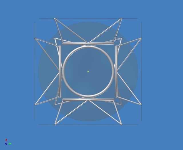
http://i299.photobucket.com/albums/mm31 ... ceView.jpg shows 5 of the 6 coils looking through the center of one.
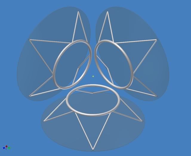
http://i299.photobucket.com/albums/mm31 ... erView.jpg shows 3 of the coils looking through the corner of the cube.
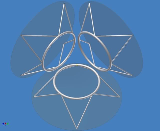
http://i299.photobucket.com/albums/mm31 ... alView.jpg shows 3 of the coils looking along a line through the center of the machine and through the mounting point of 2 struts. This is to show the shadowed strut location. The little yellow dot is the center point of the machine. But the plasma ball will have a much larger diameter that that making shadowing quite fuzzy.
The struts are splayed more that I expected them to be in order to keep them in the shadows of the coils. This is not where I would prefer them structurally though.
Until we get a better load number from the plasma boys and the B field folks I’m going to have to assume that the forces are stout but not exotic.
I still can’t see a good way to make the internal multilayer tee connections.
My favorite for ease of fabrication and inherent strength is still the 4 circuit octahedron I posted a long time ago. I know I can get that one bent after nesting. But, I’ve been working on these geometries which other folks buy into more.
I would bend these more complicated ones on tooling based on a beefed up 4-slide machine.
I will look into your slice requests when I get some time. But for now a paying job has come in.
Got to keep the boss happy.
I have not had time to catch up with the conversation but wanted to get this posted anyhow.
Baseline sizes for these pictures is 2 M coil radius 8” thick coils 4” thick struts 2 M space between the coil and the wall.
Here is a picture of how I think I would put the struts (more or less).
Trusses are a cut-and-dried structural technology.
They grey circles are mounting surfaces.
http://i299.photobucket.com/albums/mm31 ... ceView.jpg shows 5 of the 6 coils looking through the center of one.
http://i299.photobucket.com/albums/mm31 ... erView.jpg shows 3 of the coils looking through the corner of the cube.
http://i299.photobucket.com/albums/mm31 ... alView.jpg shows 3 of the coils looking along a line through the center of the machine and through the mounting point of 2 struts. This is to show the shadowed strut location. The little yellow dot is the center point of the machine. But the plasma ball will have a much larger diameter that that making shadowing quite fuzzy.
The struts are splayed more that I expected them to be in order to keep them in the shadows of the coils. This is not where I would prefer them structurally though.
Until we get a better load number from the plasma boys and the B field folks I’m going to have to assume that the forces are stout but not exotic.
I still can’t see a good way to make the internal multilayer tee connections.
My favorite for ease of fabrication and inherent strength is still the 4 circuit octahedron I posted a long time ago. I know I can get that one bent after nesting. But, I’ve been working on these geometries which other folks buy into more.
I would bend these more complicated ones on tooling based on a beefed up 4-slide machine.
I will look into your slice requests when I get some time. But for now a paying job has come in.
Got to keep the boss happy.
-Tom Boydston-
"If we knew what we were doing, it wouldn’t be called research, would it?" ~Albert Einstein
"If we knew what we were doing, it wouldn’t be called research, would it?" ~Albert Einstein
There are line cusps and point cusps. They both matter.
In WB-100 the first wall heat loading will be 1 MW/m^2. All this metal you are proposing to hold the contraption together is going to have to be cooled.
Which means sizing for strength alone is insufficient. You need to size for strength and cooling.
And then there is the torque on the "V".
In WB-100 the first wall heat loading will be 1 MW/m^2. All this metal you are proposing to hold the contraption together is going to have to be cooled.
Which means sizing for strength alone is insufficient. You need to size for strength and cooling.
And then there is the torque on the "V".
Engineering is the art of making what you want from what you can get at a profit.
Direct single pass coolant flow is NOT a benefit. It raises flow rqmts. Or delta T. And it raises delta P. Splitting the flow into six circuits helps.BUT, many of the benefits like direct, single pass coolant flow,
I can put multi-strand magnets in circular casings.are retained while the failings (single electrical conductor) are replaced with more standard multi-strand magnets.
Engineering is the art of making what you want from what you can get at a profit.