Guys,
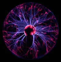
Imagine if the plasma were merely held in a glass sphere under vacuum. Place the glass sphere in the center of 6 wire coils. You could use this as a very quick, very cheap, very simple mock up system to test ideas.
Mock Up System to study the polywell
-
randomencounter
- Posts: 69
- Joined: Wed May 30, 2012 5:49 pm
So you are suggesting putting the vacuum chamber entirely within the polywell device instead of putting the polywell inside the vacuum chamber?
My first thought is that wall collisions at the cusps would be a problem, but I can see [s]why you might think that it would[/s] how it could be useful for obtaining data on the magnetic field structure.
My first thought is that wall collisions at the cusps would be a problem, but I can see [s]why you might think that it would[/s] how it could be useful for obtaining data on the magnetic field structure.
The glass layer would act as an insulating barrier that would distort the process.
This is similar to when I played with my son's plasma ball. Although, I could could not really generate high enough fields using copper and a battery charger.
This is similar to when I played with my son's plasma ball. Although, I could could not really generate high enough fields using copper and a battery charger.
The development of atomic power, though it could confer unimaginable blessings on mankind, is something that is dreaded by the owners of coal mines and oil wells. (Hazlitt)
What I want to do is to look up C. . . . I call him the Forgotten Man. (Sumner)
What I want to do is to look up C. . . . I call him the Forgotten Man. (Sumner)
Some of the EMC2 devices were like a glass sphere of plasma, but not WB 1,2,4. At leaqst not in total. The cusps wree open, though the surface area for the cusp electrons to hit was a lot more than in WB6. I'm not sure what data collections and the fidelity of the data sets before WB5, but it was the data from WB5 that bludgened Bussard, etel. into appreciating recirculation. Having said that the commercial 'plasma balls' conceivably could give some useful pictorial perspectives. As Idajo stated and I have found, the size of the magnets and strength may need to be more than a casual effort. Moving fingers, permanent magnets, etc over the ball cause interesting deformations of the plasma. The trick may be in careful attention to symmetry with large enough ring magnets to surround the plasma ball. Even then the ball electronics/ electrode structure may complicate the picture intolerably.
Dan Tibbets
Dan Tibbets
To error is human... and I'm very human.
I occurs to me that commercial plasma balls produce plasma arcs consitant with my fusor a pressures of several thousands of Miceons (~ 1/100 to 1/1000th of an atmosphere. At these pressures, the mean free path charged particle coupling, and other effects may be much different than at pressures ~ 1000 times deeper. The arcs tend to be high current (unless you are current limited as I presume the plasma balls are (probably micro amps). The interactions with magnetic fields may be significantly different. Certainly a WB is out of the question. some interesting things ay be seen, but not too much could be read into them.
Dan Tibbets
Dan Tibbets
To error is human... and I'm very human.
Guys,
All I am suggesting is, the vacuum chamber may not need to be as big as it is.
The action is happening just around the rings.
So what if the vacuum was built just outside the rings - I was imaging a glass sphere around the rings - like a space suit helmet.
The outside cage could be placed outside the glass.
The glass would act as an insulator. That would reduce the voltage keeping wayward electrons inside the rings, but it would also reduce sparks between the rings and the cage.
Trying not to sound like idiot here, but the cusps is where electrons can escape right?
Wouldn't electrons be hitting the glass at that location like crazy?
Slowly heating up the glass?
Like a plasmalamp focussing on a finger pressed against the glass.
Wouldn't electrons be hitting the glass at that location like crazy?
Slowly heating up the glass?
Like a plasmalamp focussing on a finger pressed against the glass.
Or the Arc Welder punches a neat hole in the glass...
The development of atomic power, though it could confer unimaginable blessings on mankind, is something that is dreaded by the owners of coal mines and oil wells. (Hazlitt)
What I want to do is to look up C. . . . I call him the Forgotten Man. (Sumner)
What I want to do is to look up C. . . . I call him the Forgotten Man. (Sumner)
The distance from the midplane of the magrid to the vacuum vessel wall is uncertain. In the patent application it was mentioned that the e- guns need to be placed ~ 1.5 x the magrid radius (?). With recirculation an electron traveling outward at a tiny fraction less than the escape velocity may take a considerable distance to turn around (not just a few mm).
At some point these escaping up scattered electrons need to be picked off from the cusp bordering magnetic fields so that these electrons do not reenter the magrid through a different cusp. This would set the maximum distance between the maggrid and the vacuum vessel wall (or other intercepting structure). Again this is mentioned in the patent application.
Dan Tibbets
To error is human... and I'm very human.
This point I think will plague Famulus as I have stated before. His construct will need to change to address this. Not enough space in his chamber.With recirculation an electron traveling outward at a tiny fraction less than the escape velocity may take a considerable distance to turn around (not just a few mm).
The development of atomic power, though it could confer unimaginable blessings on mankind, is something that is dreaded by the owners of coal mines and oil wells. (Hazlitt)
What I want to do is to look up C. . . . I call him the Forgotten Man. (Sumner)
What I want to do is to look up C. . . . I call him the Forgotten Man. (Sumner)
Good points. As the number of particles increase and the time intervals decrease, the accuracy goes up, as does the computational load (exponentially).
I don't know the geometry of the external magrid magnetic field lines, except that magnetic field illustrative programs seem to show dimensions of around twice to three times the radius of the magrid. This problem can be approached from both directions.The clearance must be enough to pick off some percentage of the normal energy escaping electrons, and especially the up scattered electrons. It is a choice of how much up scattering you wish to tolerate. If the magrid potential is 12,000 V and the potential well is ~ 10,000V, then this amount of u pscattering may naturally be recirculated, provided there is enough turn around distance. But the final few hundred volts of up scattering (up to 12,000 V) may consume most of the external space provided by the spacial dimensions and corresponding B field. The acceptable limit will require some portion of the total be lost. I believe the WB6 limit was ~ 90% recovery/ recirculation. How much of this was due to the space available outside of the magrid and how much of this was due to escaping electrons hitting the nubs. I presume they have a better handle on this in WB7.0 and 7.1. Perhaps their recirculation efficiency approaches closer to 20X rather than the 10X of WB6.
From the other side is arguement such as A. Carlson provided back when recirculation between cusps (electron looping around magnetic field) was still considered the mechanism for recirculation. For this to happen there would need to be greater magrid to wall distances. This would require a much larger vacuum vessel. But, my current understanding is that this condition is catastrophic as it would allow for continuous recirculation of excessively up scattered electrons. This would conserve energy but at the cost of more quickly thermalizing the electron population. You want to lose these up scattered electrons. The trick is to do so so without losing too much energy. My impression is that this margin between the potential well and the drive voltage (eg:10,000 V - 12,000 V) allows for modestly up scattered electron to be recovered and accelerated back into the magrid at a final voltage of the potential well (because of the same inefficiencies that apply to the virgin electrons). Depending on how many electron collisions (and MFP considerations) are needed to up scatter a selected electron on average, past this 20% margin may allow for both efficient recirculation and maintainance of monoenergetic chariteristics. An almost win - win situation, instead of a win- loss situation. Also remember that a portion of the escaping up scattered electron's kinetic energy is recovered by the magrid so the penalty of allowing the up scattered electrons to escape is less painful from an energy loss perspective. One of the many compromises that is necessary for positive power production.
Dan Tibbets
To error is human... and I'm very human.