Those recent posts showing the polywell using permanent toroidal magnets from a microwave oven showed the magnets held in a rack with the cross-over away from the funny cusps.
In fact...
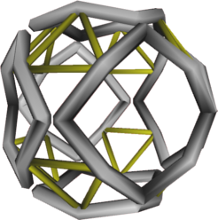
hanelyp wrote:An image I posted to the magrid brainstorming thread:
Same basic config as the cube polywell, but with the coils bent to be more 'spherical'. Is this something like what you're trying to get at?
is almost exactly what I am getting at, except I think the braces / tits / cross-overs / whatever you want to call them should be much closer to the corners.
By Dr. B's description, I think the side of the square plan-form magnets should align along the same arc of the circle with each other but that thcorners should be rounded such that they miss each other. With them aligned like that, the outside of one magnet would be aligned with the inside of the next (and vice versa) so that braces that way would form a diamond around the funny cusp.
MSimon wrote:Is the metal in the holes magnetically shielded?
Presuming you mean the coppery colored connections between the coils, the yes, sort of.
This is one of Indrek's sims, but I THINK he stated that this actually used square plan-form coils connected mid EDGE not rotated 45 degrees and connected at the corners. But even so, the general field would partially protect the cross braces placed at the locations shown.
With a smaller funny cusp, I think they could be moved closer to the funny cusp and still be protected, certainly better than the connection that is there now.
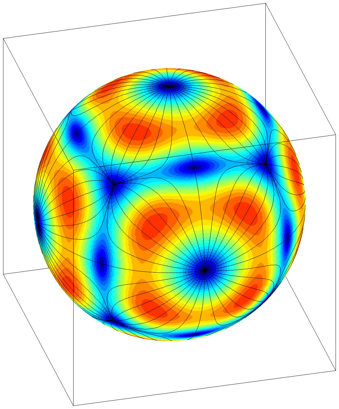
MSimon wrote:I'd like to see a field simulation of the device.
Me to! Indrek??
PS: Google count on "Polywell fusion" (no quotes) is 17,000.
Dr. Bussard said that the joints or connecters between coils was a problem, and that they had tried to minimize the detrimental effects by attaching them to the coils at a point beyond the midline (between inside and outside) and by giving them a curve to presumably keep them beyond the range of most of the cusp action. I wonder if, instead of going to seperate supports for each coil, extending these joints would be adaquite, ie- the joints would look like long 'U's instead of shallow 'C's.
D Tibbets wrote:Dr. Bussard said that the joints or connecters between coils was a problem, and that they had tried to minimize the detrimental effects by attaching them to the coils at a point beyond the midline (between inside and outside) and by giving them a curve to presumably keep them beyond the range of most of the cusp action. I wonder if, instead of going to seperate supports for each coil, extending these joints would be adaquite, ie- the joints would look like long 'U's instead of shallow 'C's.
Dan Tibbets
Mechanically that is a rather fine oscillator: moving mass, energy storage in the bent "U".
Engineering is the art of making what you want from what you can get at a profit.
D Tibbets wrote:Dr. Bussard said that the joints or connecters between coils was a problem, and that they had tried to minimize the detrimental effects by attaching them to the coils at a point beyond the midline (between inside and outside) and by giving them a curve to presumably keep them beyond the range of most of the cusp action. I wonder if, instead of going to seperate supports for each coil, extending these joints would be adaquite, ie- the joints would look like long 'U's instead of shallow 'C's.
That had been my thought too, but it would still be in the primary electron flow path of the funny cusp so I had proposed that they be made non-conductive and allowed to accumulate some of the charge they saw and thus become a point rejector of electrons. Soemone suggested that might thereby make them a point attractor for the ions so I had another think.
MSimon wrote:Mechanically that is a rather fine oscillator: moving mass, energy storage in the bent "U".
Sing a song of fusion, a poly full of try... What would drive the oscillation?
TallDave wrote:Me too. I don't see how it can confine anything when the sides don't face each other.
Well here may be where our understandings of the unit depart. It seems that you are looking to the cusps to do some sort of confinement. Not so. The cusps just provide directed leakage and re-entry paths that avoid the MaGrid can. The confinement is the positive charge on the MaGrid.
Away from the cusps, the electrons reflect off the mirror, no?
Hrm, I had thought Bussard was referring to the corners of the cube the coil casing form the sides of, but upon closer inspection a "corner" is, less intuitively, where two coils meet. So we have:
-- 6 point cusps at the center of the coils
-- 12 "funny cusps" where the coils meet each other
Interestingly, Bussard thought the interconnects could be shielded too.
electric field-enhancing sharp corners and small areas. Poorly
shielded areas, such as the interconnects between spaced
corners of the coil systems, can be minimized by careful
design to minimize area and avoid sharp corners, and by use
of internal B fields produced by current carriers through the
interconnects
Well here may be where our understandings of the unit depart. It seems that you are looking to the cusps to do some sort of confinement. Not so. The cusps just provide directed leakage and re-entry paths that avoid the MaGrid can. The confinement is the positive charge on the MaGrid.
Not quite. You don't need 1e5 confinement from the cusps, but you do need 1e3 containment.
As previously noted, no Polywell can operate at all if arcing
occurs outside the machine, between the walls and the
machine, because this destroys the ability of the driving
power supplies to produce deep potential wells. Thus the
mean free path for ionization outside the machine (inside the
container) must be much greater than the external
recirculation factor, times the machine-to-wall distance.
Since the mfp for ionization is inversely proportional to the
product of the local neutral density and the ionization crosssection,
this condition can ALWAYS be satisfied, IF the
external neutral gas pressure is made sufficiently small. In
order to avoid external arcing, the densities thus required are
very much too low to be of interest for fusion, thus the
density inside the machine (at its boundary) must be very
much higher than that outside. This ratio is the Gmj factor,
which is the ratio of electron lifetimes within the machine
with B fields on, to that without any B fields.
In contrast, in order to be of interest for fusion, the interior
density must be above some numerical value for any given
size of machine. Typically this requires electron densities at
the interior boundary of order 1E13/cm3, or higher. While
the exterior densities (of neutrals able to be ionized) must
typically be below 1E10/cm3 or less. Thus a minimum value
exists for Gmj (here, typically 1E3), below which no
machine can give significant fusion or net power,
independent of the unprotected wall loss problem. Both
must be solved simultaneously
The magnetic fields don't just shield the Magrid. They also provide enough confinement that you have a 1000:1 ratio inside:outside.
Charged particles with a velocity component perpendicular to the field will gyrate around a field line in a generally circular or helical orbit and thus sample some of the field lines that are converging to create the field gradient. The radial component of these field lines, coupled with the azimuthal motion of the particle, will result in a force parallel to the field and directed toward the region of smaller field strength.
In the sixties and seventies, machines using magnetic mirror confinement were considered a viable candidate for producing fusion energy. The concept was eventually largely abandoned because it proved to be impractical to maintain the necessary non-Maxwellian velocity distribution. Collisions scattered the charged particles so that the pitch angle was too small for containment. In addition, velocity space instabilities contributed to the escape of the plasma. (For a modern attempt, see the Polywell inertial electrostatic confinement design by Robert Bussard.)
MSimon wrote:Is the metal in the holes magnetically shielded?
I'll defer to any decent simulation or experimental work, but I specifically placed the interconnects away from the known cusps, so they should be shielded.
I count
* 6 point cusps coil center.
* 8 point cusps centered on the triangular faces between the coils.
* 12 funny cusps where coils meet.
MSimon wrote:Mechanically that is a rather fine oscillator: moving mass, energy storage in the bent "U".
Well, it could make a good tuning fork, though with the 12 connections between the 6 magrids you would have ample oppertunity to 'detune' the system so any vibrations could be dampened. This, along with stiff, possibly braced connections (bracing being located in the magrid shadow, with the assumption that recirculation is primarily through ossilation through the same cusps, not orbiting) gives the option of not hanging each magrid off the vessel wall, or alternatly using both support systems to resist the weight and repelling forces of the magnets in a large machine.