This is very difficult to explain without pictures. Take a car tire and split it into two pieces so that you now have two water troughs. While building the electromagnet, the wire would be laid down in one trough and the the second trough would be laid on top of it and then the seam around the perimeter would be welded up.
So long as that assembly is lying flat on an even surface, the coil is in compression the way we want it to be in compression when it is fighting the fields of its fellow magnets. Two of the magnets, the top one and the bottom one, will see very similar stresses all the time. The four upright magnets, on the other hand, see a variety of stresses, depending on the stage of startup. So long as the cores are warm, it's not that big a deal except that you want the structure to prevent the coils from going egg-shaped. That means that the structures supporting the coils must be stiff enough not to go egg shaped. This is not as simple as it seems at frist blush.
All six of the coils will undergo noticeable contraction and dangerous embrittlement as the temperature falls. The structure holding the coils will undergo contraction and embrittlement as well. Chilling the two inner cooling jackets (LHe and LN2), will have to be done very slowly.
Because we can use only a very limited number of structural elements to maintain these conditions, we are obliged to construct a very stiff structure, ie, torii with heavy walls. Ordinarily, a large number of structural members in tension would be used for this job, but such members would interfere with what the machine is intended to do. They would catch our subatomic beasties and play havoc with the shape of the magnetic fields.
I don't know what the magnitude of the resultant forces will be yet, save to say that they will be fairly large and will have a one meter lever arm to work against the mounts of the four upright magnets. That means that the outermost water jacket will see a lot of torgue.
We're gonna have 60T total to worry about here. What we are doing, in essence, is driving large wedges into each face of a cubical box. Fortunately, the wedges are springy. It won't be possible to say what the total force will be until the separationg between the coils will be. It is hard to determine what that will be until the sizes and wall thicknesses of the supporting structure will be. This is necessarily an interative process and I have not yet gotten to the point where I can give you any useful information on it.
We have four coolants to get into the structure and out of it. We have LHe, LN2, Cool Water and Hot Water. All four cooling jackets are separated by vacuum jackets that act as insulators. This will introduce some intricacies to the structure that will have to be dealt with. They will add stresses that would otherwise not be present and they may well cause problems with hot spots.
Because I am not up on the math necessary to do a good job of finite element analysis, I am proposing to draw the first picture to get us started. Feedback from the FEA, will then call for changes to the picture. We repeat the process until we have what appears to be a workable structure. Pumps and plumging will also have to be sized during this process. We will also have to be on the lookout for hot spots and avenues of conduction to the LHe filled core.
At the moment I am acquainting myself with the wonderfully rich user interface of Blender so that I can accurately model the Magrid. Blender is not a drafting package per se, but it has not cost me anything and it does handle scaling in a fairly straightforward manner. If I had the money I'd buy a copy of Autocad, but I don't and I think we can get by without a drafting package at this point in time.
The goal here is to just get a start. Detailed engineering won't take place for a several years.
Is There an Optimal Size for Magrid Casings?
Just to throw a monky wrench into the works- actually need a three track approach:
1) liquid nitrogen cooled copper coils for Breakeven Demo BSR with limited operating and lifetimes.
2) liquid heluim cooled super conducter coils.
3) liquid nitrogen cooled high temperature superconducter coils- if neutron tolerant versions become aviable in the next 5 years (optamistic approach).
Dan Tibbets
To error is human... and I'm very human.
Billy,
Since most of the stress is going to be transmitted from the magnet (LHe containing) cases any way - if you need thick walls for stress problems put them there. I believe there are some SSs that are pretty good at LN2 temps. I'm not familiar with LHe. But consider this: The Navy is testing a nearly 40 MW motor using LHe ot 32K. I'm thinking 20K for what we want to do or maybe even 4K if necessary to get the magnetic field up. Any way - shock and vibration are well known specs for all Naval Vessels since WW2. (there was a bunch of electrical eqpt (IIRC) that didn't work well when the ship took a near miss. I believe Rickover took an interest in this and got the problem corrected. If the piece to be tested is big enough real explosions have to be used (still) to test eqpt. For the smaller pieces of eqpt there are shock and vibration simulators.
BTW there is a FEM program that is user maintained that you can get for free.
The link to that along with some others that may be of interest can be found here:
http://iecfusiontech.blogspot.com/2008/ ... n-fem.html
For initial cool down pump LN2 into the space between the LHe and the LN2 sections. Pull a vacuum on the LN2 and Cool Water
And yes - a preliminary design is an excellent idea.
I'm doing a schematic/block diagram of the pumping system and required instrumentation. I'll put something up when I get them drawn up.
Engineering is the art of making what you want from what you can get at a profit.
-
Billy Catringer
- Posts: 221
- Joined: Mon Feb 02, 2009 2:32 pm
- Location: Texas
D Tibbets wrote:Just to throw a monky wrench into the works- actually need a three track approach:
1) liquid nitrogen cooled copper coils for Breakeven Demo BSR with limited operating and lifetimes.
2) liquid heluim cooled super conducter coils.
3) liquid nitrogen cooled high temperature superconducter coils- if neutron tolerant versions become aviable in the next 5 years (optamistic approach).
Dan Tibbets
Agreed. All of those tests can be done on different versions of the model. The differing versions will not be too terribly difficult once we have a basis to start from.
-
Billy Catringer
- Posts: 221
- Joined: Mon Feb 02, 2009 2:32 pm
- Location: Texas
MSimon wrote:Billy,
Since most of the stress is going to be transmitted from the magnet (LHe containing) cases any way - if you need thick walls for stress problems put them there. I believe there are some SSs that are pretty good at LN2 temps. I'm not familiar with LHe. But consider this: The Navy is testing a nearly 40 MW motor using LHe ot 32K. I'm thinking 20K for what we want to do or maybe even 4K if necessary to get the magnetic field up. Any way - shock and vibration are well known specs for all Naval Vessels since WW2. (there was a bunch of electrical eqpt (IIRC) that didn't work well when the ship took a near miss. I believe Rickover took an interest in this and got the problem corrected. If the piece to be tested is big enough real explosions have to be used (still) to test eqpt. For the smaller pieces of eqpt there are shock and vibration simulators.
BTW there is a FEM program that is user maintained that you can get for free.
The link to that along with some others that may be of interest can be found here:
http://iecfusiontech.blogspot.com/2008/ ... n-fem.html
For initial cool down pump LN2 into the space between the LHe and the LN2 sections. Pull a vacuum on the LN2 and Cool Water
And yes - a preliminary design is an excellent idea.
I'm doing a schematic/block diagram of the pumping system and required instrumentation. I'll put something up when I get them drawn up.
I'm on it, Chief. Don't expect to hear from me for a few hours today. I'm still rasslin' with Blender.
Billy Catringer wrote:This is very difficult to explain without pictures. Take a car tire and split it into two pieces so that you now have two water troughs. While building the electromagnet, the wire would be laid down in one trough and the the second trough would be laid on top of it and then the seam around the perimeter would be welded up.
Billy,
Seems we keep talking past each other. The magnet I described before, and as seen in the following:
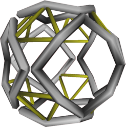
is NOT like a tire. Also, remember that I said the real one would be slightly different. The sides would be true arcs, following the curve of the sphere. They would also be aligned along the same line of the sphere. The corners would have to be more curved to miss each other.
With that, there is very little in bending. It is almost all in hoop stress.
Kiteman:
My intuition says going away from circular magnets will be fraught.
I think there is a topological problem with this concept. Any great circles on a sphere, that meet at right angles (on the tangent of the sphere) will form a triangle on the sphere, not a square.The sides would be true arcs, following the curve of the sphere. They would also be aligned along the same line of the sphere.
My intuition says going away from circular magnets will be fraught.
A few thoughts:
Hanging the cube from one corner makes the buckling forces on the supports smaller.
This may allow us to reduce cross sections.
It also simplifies the design by making all the coils structurally equivalent.
See page 14 of this for a picture. http://www.askmar.com/Fusion_files/EMC2 ... plants.pdf
The tension in the SC that Billy is concerned about is along the length of the SC wire i.e. we don’t want to stretch it.
Welcome Billy!
The tension on the SC is dependent on the relative thermal expansion coefficients of the SC wire vs its support (and of course between all the other layers too).
The mechanical loads from the B fields are directly on the SC itself.
The technique of transferring that load across several layers of vacuum to ground it to the strength members is pretty sketchy as is the fabrication process.
Those are just a couple of the larger pieces of the puzzle to keep in mind.
Turbulence = vibration good call.
Another reason we need to keep the SC from moving is that the plasma guys are saying that they need to balance the fields very precisely. That will be hard to do if the wires are squirming around. Not to mention cracking and arcing.
A reason for hot water (rather than supercritical steam or NaK) outer coolant is the larger delta T across a given thickness of the outer tube(shell) moves more heat across the outer shell from the fixed max temperature of the outer surface <1000C absolute max for Cu to the coolant.
Not only that but, more pressure from supercritical h2o requires thicker copper shell which in turn reduces the heat flow.
This also causes 4 cm thick outer shell to be a no-can-do. Therefore the structural layer will have to be an inner one, preferably one at a reasonable temperature, not too cold, not too hot.
Heat flow and therefore current flow is complicated by the fact that almost all of the heat is deposited on one half of the circumference. My thought has always been to guide the water into a spiral path by wrapping a spring around the inner tube before bending the tubes to shape. This is the classic tool to keep tubes from kinking during bending too.
This raises pressure drops, but my calc’s show coolant pressure drops to be minimal anyway.
When planning coolant paths we need to be aware of the need for the removal of bubbles entrained in the coolants. (especially if they are being operated near their boiling points)
That is a point toward using supercritical pressures.
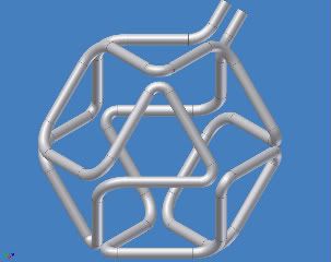
If you take the above pictured coils and reconnect the corners you can make it in one pass. Like this.
 bigger picture here-> http://i299.photobucket.com/albums/mm31 ... ube1-2.jpg
This would simplify the piping and current flows considerably.
The pipes should probably be bowed to follow the surface of the sphere but this was easier to draw and it will be easier to model the fields from it.
There may (or may not) be some issues with it, as discussed this same picture when I posted some time ago on the Magrid Brainstorming thread. It is the same configuration as one of Dr Bussard’s experiments (MPG) that was said to work well with current limitations (that I think we can address).
The squares could be made more circular, but I think opposing forces from adjacent faces would balance and cause the straighter sections to have less stress along the surface of the sphere, leaving the only mechanical forces in the radial direction.
Yes, anything other than a simple torus complicates the field calculations, but whether the effect on performance is positive or negative is unknown.
MSimon, Where on photobucket were the pictures referred to above? I can’t seem to find them with their search nor was there a link in this thread (that I found).
Hanging the cube from one corner makes the buckling forces on the supports smaller.
This may allow us to reduce cross sections.
It also simplifies the design by making all the coils structurally equivalent.
See page 14 of this for a picture. http://www.askmar.com/Fusion_files/EMC2 ... plants.pdf
The tension in the SC that Billy is concerned about is along the length of the SC wire i.e. we don’t want to stretch it.
Welcome Billy!
The tension on the SC is dependent on the relative thermal expansion coefficients of the SC wire vs its support (and of course between all the other layers too).
The mechanical loads from the B fields are directly on the SC itself.
The technique of transferring that load across several layers of vacuum to ground it to the strength members is pretty sketchy as is the fabrication process.
Those are just a couple of the larger pieces of the puzzle to keep in mind.
Turbulence = vibration good call.
Another reason we need to keep the SC from moving is that the plasma guys are saying that they need to balance the fields very precisely. That will be hard to do if the wires are squirming around. Not to mention cracking and arcing.
A reason for hot water (rather than supercritical steam or NaK) outer coolant is the larger delta T across a given thickness of the outer tube(shell) moves more heat across the outer shell from the fixed max temperature of the outer surface <1000C absolute max for Cu to the coolant.
Not only that but, more pressure from supercritical h2o requires thicker copper shell which in turn reduces the heat flow.
This also causes 4 cm thick outer shell to be a no-can-do. Therefore the structural layer will have to be an inner one, preferably one at a reasonable temperature, not too cold, not too hot.
Heat flow and therefore current flow is complicated by the fact that almost all of the heat is deposited on one half of the circumference. My thought has always been to guide the water into a spiral path by wrapping a spring around the inner tube before bending the tubes to shape. This is the classic tool to keep tubes from kinking during bending too.
This raises pressure drops, but my calc’s show coolant pressure drops to be minimal anyway.
When planning coolant paths we need to be aware of the need for the removal of bubbles entrained in the coolants. (especially if they are being operated near their boiling points)
That is a point toward using supercritical pressures.
If you take the above pictured coils and reconnect the corners you can make it in one pass. Like this.
bigger picture here-> http://i299.photobucket.com/albums/mm31 ... ube1-2.jpg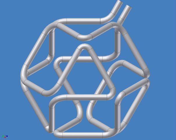
This would simplify the piping and current flows considerably.
The pipes should probably be bowed to follow the surface of the sphere but this was easier to draw and it will be easier to model the fields from it.
There may (or may not) be some issues with it, as discussed this same picture when I posted some time ago on the Magrid Brainstorming thread. It is the same configuration as one of Dr Bussard’s experiments (MPG) that was said to work well with current limitations (that I think we can address).
The squares could be made more circular, but I think opposing forces from adjacent faces would balance and cause the straighter sections to have less stress along the surface of the sphere, leaving the only mechanical forces in the radial direction.
Yes, anything other than a simple torus complicates the field calculations, but whether the effect on performance is positive or negative is unknown.
MSimon, Where on photobucket were the pictures referred to above? I can’t seem to find them with their search nor was there a link in this thread (that I found).
-Tom Boydston-
"If we knew what we were doing, it wouldn’t be called research, would it?" ~Albert Einstein
"If we knew what we were doing, it wouldn’t be called research, would it?" ~Albert Einstein
Coil winding:
Winding the coil is much easier on a core (inside its id) that is on the inside of the axle side of the “innertube”.
But the forces are going to be against the “tread” side of the “innertube”.
We want to lay them down with enough slack so they don’t get stretched but we don’t want them to move when we apply current in their slack condition.
The only way I see to do it is to lay them inside the “tire”, maybe gluing them in place as they are laid up, but now we have glue in the cryogenic zone.
Maybe the support structure could be shrunk onto the coil after it is formed.
Maybe the SC manufacturer can incorporate high tensile steel wires inside the tape or built up wire alongside the SC strands themselves.
Maybe the coils could be all assembled. Then we could apply a current to them (don’t they have a copper or steel carrier swaged onto them?) to seat them in the support structure while they are at a relatively malleable temperature. Then while under current they could be stabilized with some kind of slurry and fired (gently!) to hold them in place. I’m imagining something like plaster of paris but designed for cryogenics. I don’t know if it exists but I know refractory versions do.
It also has to match their thermal expansion coefficient.
This material could be a nightmare.
Hey, what do they use to insulate the LH2 tanks on rockets? It sprays on and sets up fairly strong.
Can Of Worms.
-Tom Boydston-
"If we knew what we were doing, it wouldn’t be called research, would it?" ~Albert Einstein
"If we knew what we were doing, it wouldn’t be called research, would it?" ~Albert Einstein
Dr. B's intuition told him to do it, though his did not follow the sphere's surface but the polyhedron's edge.icarus wrote:Kiteman:I think there is a topological problem with this concept. Any great circles on a sphere, that meet at right angles (on the tangent of the sphere) will form a triangle on the sphere, not a square.The sides would be true arcs, following the curve of the sphere. They would also be aligned along the same line of the sphere.
My intuition says going away from circular magnets will be fraught.
Also, while I said corner, I did not say right angle. The "square plan-form" when mapped onto the sphere, may have other than 90 degree angles, though in the special case here, I am not sure about that. Simplistically speaking from a latitude longitude coordinate system, the square goes from (0, +45) to (45, 0) to (0, -45) to (-45, 0). And again, the corners are rounded sufficiently to miss the actual points.
YES. This is almost perfect except the sides should be aligned a bit more, though it is fairly hard to tell with this viewpoint. You will almost certainly need ties at each of the vertices.tombo wrote:
This would simplify the piping and current flows considerably.
The pipes should probably be bowed to follow the surface of the sphere but this was easier to draw and it will be easier to model the fields from it.
The MPG was a single run of tubing that was actually touching at the verticies, no? This should be a lot better.There may (or may not) be some issues with it, as discussed this same picture when I posted some time ago on the Magrid Brainstorming thread. It is the same configuration as one of Dr Bussard’s experiments (MPG) that was said to work well with current limitations (that I think we can address).
Please bow them, but not make them circular. I think it will improve the funny cusp performance.The squares could be made more circular, but I think opposing forces from adjacent faces would balance and cause the straighter sections to have less stress along the surface of the sphere, leaving the only mechanical forces in the radial direction.
Winding square plan-form bowed coils is practically as easy.tombo wrote:Coil winding:
Winding the coil is much easier on a core (inside its id) that is on the inside of the axle side of the “innertube”.
Or in a rack that gets placed into the "tire" afterwords, thought that is the funkiest looking tire I've ever seen; square with bowed sides.But the forces are going to be against the “tread” side of the “innertube”.
We want to lay them down with enough slack so they don’t get stretched but we don’t want them to move when we apply current in their slack condition.
The only way I see to do it is to lay them inside the “tire”, maybe gluing them in place as they are laid up, but now we have glue in the cryogenic zone.
American Superconductor already does on their 2nd generation HTSC wires (model 344S), and at least one Japanese firm is doing a similar thing with MgB.Maybe the SC manufacturer can incorporate high tensile steel wires inside the tape or built up wire alongside the SC strands themselves.
-
Billy Catringer
- Posts: 221
- Joined: Mon Feb 02, 2009 2:32 pm
- Location: Texas
KitemanSA wrote:
Billy,
Seems we keep talking past each other. The magnet I described before, and as seen in the following:...image snipped...is NOT like a tire. Also, remember that I said the real one would be slightly different. The sides would be true arcs, following the curve of the sphere. They would also be aligned along the same line of the sphere. The corners would have to be more curved to miss each other.
With that, there is very little in bending. It is almost all in hoop stress.
I understand that what you propose is nothing like a tire. I also understand that you are proposing a smoother figure that would, without doubt, do a better job of trapping electrons and encouraging nucleii to meet up in the center.
The trouble we are confronted with is that we have have some structural requirements that must be met. The SC cores are going to be dangerously brittle at LHe temperatures. The reason I am talking about tire-like shapes is to insure that the stresses placed on the cores can always be evenly distributed in compression. Any other form of stress, including tension, will likely cause fractures in the SC cores.
I have spent a little time, not enough, looking at the safety side of this thing. Superconducting magnets fail more along the lines of Mount Saint Helens than they do Kilauea.
I apologize for confusing you and probably everyone else with the term hoop stress while using the word hoops. Hoops was me getting south in the mouth while talking about torii. Hoop stress comes from internal pressure, as in situations wherein you have fluids at high temperatures and pressures trapped in a vessel with a circular cross section.
When you stand a torus up on its edge in a 1G field, it is wont to go egg-shaped. The structure has to be stiff enough to eliminate most of this deflection. We will otherwise have trouble with magnetic alignment that effects particle paths and we also have oddball and unpredicted stresses placed on the supporting structure of the magnets.
I'm gonna hafta sit down and write down very clearly what I am worrying about. I am trying to stuff too many ideas into these little messages.